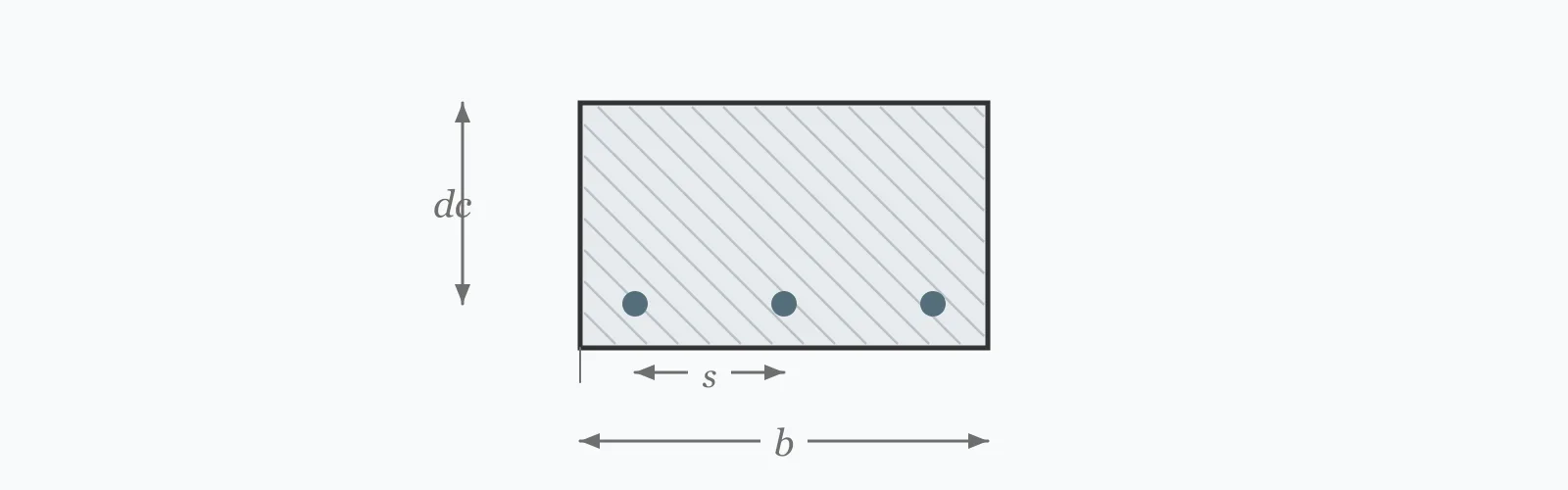
Flexural crack width depends on how hard the steel is working and how far the concrete surface sits from the nearest bar. The Gergely-Lutz expression estimates it from the service steel stress, cover and bar spacing. Enter all three to get the likely surface crack width in millimetres and an exposure classification.
Calculator
Units:
MPa
Under service load — commonly around 0.6·fy
mm
From the tension face to the nearest bar surface
mm
Centre-to-centre spacing of the tension bars
Calculation Result
Press Calculate for the estimated surface crack width and an exposure classification: 1 suits exterior exposure, 2 interior only, 3 exceeds both. Treat it as an estimate — real crack widths scatter widely around any prediction.
Step-by-Step Solution
Preliminary design aid. Results follow the published formulas cited
below and are intended for estimating, study and early design. Final design must be
verified by a licensed Professional Engineer against the code in force for your project.
Key Benefits
✓Implements the Gergely-Lutz expression in metric form
✓Returns an exposure classification alongside the numerical width
✓Makes the dominant role of steel stress explicit
✓Compares against the crack width limits used across the main codes
✓Sensitivity chart shows the near-linear response to steel stress
✓Shareable links and CSV export for serviceability records
What Is Crack Width Estimator?
When a reinforced concrete member bends, the concrete on the tension face cracks at a fraction of the load the steel can carry — typically well below service level. The steel then carries the tension across the crack, and the crack opens in proportion to how much the steel stretches. Gergely and Lutz fitted an expression to laboratory data relating the surface crack width to steel stress, the concrete cover to the bar centre, and the effective tension area of concrete surrounding each bar.
Why cover cuts both ways
Thicker cover protects reinforcement from corrosion, which is the whole reason for specifying it. But it also puts the concrete surface further from the bar restraining it, so cracks at the surface open wider. This is a genuine design tension: the durability requirement that demands more cover simultaneously worsens the crack widths that durability also cares about. It is resolved by distributing the steel more finely, not by reducing cover.
Steel stress is what you actually control
Crack width is nearly proportional to service steel stress, so it is the most direct lever. Adding reinforcement lowers the stress each bar carries at the same moment, and the cracks narrow in proportion. This is why water-retaining structures are often reinforced far beyond their strength requirement — the extra steel is bought entirely to hold the service stress down and the cracks fine.
Formula
w = 1.085×10⁻⁵ · β · f_s · ∛(d_c · A)
Gergely-Lutz crack width in mm, with fs in MPa and dimensions in mm
Related Formulas
d_c = cover + d_b/2
A = 2 · d_c · s
β ≈ 1.2
s ≤ 380(280/f_s) − 2.5c_c
Variable Definitions
Symbol
Variable
Unit
Description
w
Crack Width
mm
Estimated width of the flexural crack at the concrete surface.
f_s
Service Steel Stress
MPa
Steel stress under service load, often taken as about 60% of yield. The dominant variable.
cover
Clear Cover
mm
Concrete from the tension face to the nearest bar surface, set by durability and fire requirements.
s
Bar Spacing
mm
Centre-to-centre spacing of the tension bars.
d_c
Cover to Bar Centre
mm
Clear cover plus half the bar diameter, assumed here to be 16 mm.
β
Strain Gradient Factor
—
Ratio of neutral axis distances, taken as 1.2 for beams and slabs of ordinary proportions.
How to Use This Calculator
Use the service steel stress, not the yield strengthCracking is a serviceability check, so the stress is that under unfactored service load. A common approximation is 0.6·fy, giving about 250 MPa for Grade 420 steel, but computing it from the actual service moment is better.
Enter the clear cover to the bar surfaceThe calculator adds half a bar diameter internally to reach the bar centre. It assumes a 16 mm bar; for markedly different sizes, the assumption introduces a small error in the cover term.
Enter the tension bar spacingUse the centre-to-centre spacing of the bars in the tension face. Closer spacing distributes the same total movement into more, finer cracks, which is the whole mechanism of crack control.
Read the classification alongside the widthClass 1 suits exterior exposure, class 2 interior only, class 3 exceeds both. These follow the historical ACI guidance of 0.3 mm exterior and 0.4 mm interior.
Check the current code rule as wellACI 318 now controls cracking through a maximum bar spacing rather than a computed width. Satisfy that rule for compliance, and use this calculation to understand the mechanism or where a numerical crack width is specified.
Worked Examples
Example 1
A reinforced concrete beam has 40 mm clear cover, 16 mm bars at 150 mm centres, and a service steel stress of 250 MPa. Estimate the flexural crack width.
Step-by-Step Solution
Cover to the bar centre: dc = 40 + 16/2 = 48 mm
Effective tension area per bar: A = 2 × dc × s = 2 × 48 × 150 = 14,400 mm²
Product for the cube root: dc × A = 48 × 14,400 = 691,200
Cube root: ∛691,200 = 88.4
Crack width: w = 1.085×10⁻⁵ × 1.2 × 250 × 88.4
w = 0.288 mm
Classification: 0.288 mm falls below the 0.3 mm exterior limit, so class 1 — acceptable for exterior exposure.
Note how close it is: a service stress of 265 MPa rather than 250 would push it past 0.3 mm and into interior-only territory.
Example 2
The same beam, but the durability requirement raises cover from 40 mm to 65 mm. This is the case where protecting the steel makes the surface cracking worse.
Crack width: w = 1.085×10⁻⁵ × 1.2 × 250 × 116.9 = 0.381 mm
Classification: 0.381 mm exceeds the 0.3 mm exterior limit, so class 2 — interior exposure only
Comparison: increasing cover by 62% widened the surface crack by 32%, from 0.288 to 0.381 mm, and moved the member out of its own exposure class.
The resolution is not less cover. Reducing the bar spacing from 150 to 100 mm at the same 65 mm cover brings the width back to 0.332 mm, and adding steel to drop the service stress to 220 MPa brings it to 0.335 mm. Either lever works; reducing cover would defeat the durability requirement that raised it.
Steel Stress Sensitivity
Crack width is directly proportional to steel stress, so the curve is a straight line through the origin — which is exactly why adding reinforcement to lower the stress is the standard remedy. Watch where it crosses 0.3 and 0.4 mm. The marker shows your current stress.
Estimated Crack Width vs Service Steel Stress (fs)
Recomputed live from your inputs. The marker shows your current value.
Line chart of Estimated Crack Width against Service Steel Stress (fs). The same
values are listed in the data table below.
Values plotted above, sampled across the service steel stress (fs) range.
How to Interpret Your Results
Crack width limits are durability conventions rather than structural ones, and they vary considerably between codes and exposure conditions. The bands below follow the historical ACI thresholds the calculator's classification uses.
An estimated width of your result mm is fine enough for aggressive environments, including the tighter limits applied to water-retaining and marine structures. Cracks this narrow tend to self-heal through autogenous carbonation.
Estimated Crack Width: 0.2 – 0.3Acceptable for exterior exposure
An estimated width of your result mm falls within the 0.3 mm limit historically applied to exterior exposure. Note the scatter: real crack widths vary widely around any prediction, so leave margin rather than designing to the limit.
Estimated Crack Width: 0.3 – 0.4Interior exposure only
An estimated width of your result mm exceeds the 0.3 mm exterior limit but stays within 0.4 mm for interior conditions. For anything exposed to weather or moisture, reduce the service steel stress or the bar spacing.
Estimated Crack Width: ≥ 0.4Exceeds normal crack width limits
An estimated width of your result mm is beyond the limits for both interior and exterior exposure. Cracks this wide are visible, admit moisture and accelerate reinforcement corrosion. Add steel to lower the service stress, or use smaller bars at closer centres.
Common Mistakes to Avoid
Using the yield strength as the steel stress
Why it matters:Cracking is a service condition, and the steel is nowhere near yield under service load. Entering 420 MPa instead of a realistic 250 MPa overstates the crack width by around 68%.
✓How to avoid it:Use the service stress from the unfactored moment, or the 0.6·fy approximation. The result is nearly proportional to this input, so it deserves care.
Reducing cover to control cracking
Why it matters:It works arithmetically — less cover gives narrower surface cracks — but it defeats the durability requirement the cover exists to satisfy. Corrosion protection matters more than crack appearance.
✓How to avoid it:Keep the cover the exposure demands and control cracking through bar distribution: smaller bars at closer centres, or more steel to lower the service stress.
Treating the predicted width as accurate
Why it matters:Gergely-Lutz was fitted to laboratory data with substantial scatter. Real crack widths commonly vary by ±50% around the prediction, since cracking depends on local concrete strength, bar position and restraint.
✓How to avoid it:Treat it as an order-of-magnitude indicator. Leave margin against the limit rather than designing to it, and where crack width genuinely governs, follow the specialist provisions for water-retaining structures.
Assuming ACI still requires a crack width calculation
Why it matters:ACI 318 removed the explicit calculation in 2000, replacing it with a maximum bar spacing rule that achieves the same end more reliably. Presenting a computed width as an ACI compliance check misstates the code.
✓How to avoid it:Satisfy the §24.3.2 spacing rule for compliance. Use the crack width calculation for understanding, for Eurocode work, or where a project specification names a numerical limit.
Ignoring cracking from restraint rather than load
Why it matters:Early-age thermal contraction and drying shrinkage crack concrete whether or not it is loaded, and in a restrained wall or slab those cracks often dominate. This calculation covers flexural cracking only.
✓How to avoid it:For walls, water-retaining structures and long restrained slabs, use the restraint cracking provisions of EN 1992-3 or the equivalent, which address a different mechanism entirely.
Comparing against the wrong limit
Why it matters:Crack width limits vary by code and exposure: 0.3 mm exterior and 0.4 mm interior historically in ACI, 0.3 mm for most Eurocode reinforced concrete, and as low as 0.05 to 0.2 mm for water-retaining structures under Eurocode 2 Part 3.
✓How to avoid it:Take the limit from the governing code and the actual exposure class, not from a remembered figure. Water-retaining and marine limits are far stricter than building ones.
Practical Applications
▸Checking serviceability cracking in beams and slabs
▸Assessing crack width in exposed and marine structures
▸Judging whether observed cracking in a structure is within expectation
▸Comparing bar distribution options at equal steel area
▸Estimating the reinforcement needed to meet a numerical crack limit
▸Supporting Eurocode crack width verification
Industry Use Cases
Water-retaining structures
Tanks and reservoirs are governed by crack width rather than strength, with limits as low as 0.05 mm where tightness is required. Reinforcement is routinely two or three times what the strength calculation demands, bought entirely to hold service stress down.
Marine and infrastructure
Chloride ingress through cracks is the dominant durability mechanism for coastal structures. Designers combine tight crack limits with generous cover, and resolve the resulting tension by distributing the steel finely rather than by trading one against the other.
Structural investigation
When cracks are reported in an existing structure, comparing measured widths against the prediction for the as-built reinforcement indicates whether the cracking is normal flexural behaviour or a sign of overload, restraint or a detailing error.
Expert Tips
💡Crack width is nearly proportional to steel stress — adding steel is the most direct control available.
💡Small bars at close centres beat large bars at wide centres for the same steel area.
💡Thicker cover widens surface cracks; resolve the conflict by distributing steel, never by cutting cover.
💡Expect ±50% scatter around any prediction. Leave margin rather than designing to the limit.
💡ACI now controls cracking by maximum bar spacing, which is a more reliable rule than a computed width.
💡Restraint cracking in walls and slabs is a different mechanism and needs its own provisions.
Advantages & Limitations
Advantages
✓Captures the three variables that actually control flexural crack width
✓Gives a numerical estimate where a specification names a limit
✓Makes the cover-versus-crack-width tension explicit and quantifiable
✓Fast enough to compare bar distribution options during detailing
✓Useful for interpreting observed cracking in existing structures
Limitations
!An empirical fit with substantial scatter — expect ±50% variation in reality
!Superseded in ACI 318 by a maximum bar spacing rule since 2000
!Assumes a 16 mm bar diameter in computing the cover to bar centre
!Assumes β = 1.2, appropriate to ordinary beams but not to all sections
!Covers flexural cracking only, not restraint, shrinkage or thermal cracking
!Takes no account of long-term crack widening under sustained load
!Not applicable to prestressed concrete, which has its own decompression criteria
Crack Width Limits by Code and Exposure
Limits are durability conventions rather than structural thresholds, and they differ substantially. Water-retaining structures are the strictest by a wide margin, which is why they are so heavily reinforced.
Indicative limits. The governing code and the project specification take precedence, and water-retaining limits vary with the hydraulic gradient.
For reinforced concrete in ordinary buildings, 0.3 mm exterior and 0.4 mm interior are the historical ACI limits, and Eurocode 2 uses 0.3 mm for most exposure classes. Water-retaining structures require far less, in some cases as little as 0.05 mm.
What causes cracks in reinforced concrete?
Flexural cracking under load is normal and expected — it is how the reinforcement gets engaged. Cracks also arise from drying shrinkage, early-age thermal contraction, restraint and corrosion, and those mechanisms need different treatment from flexural cracking.
Does more cover mean wider cracks?
At the surface, yes. Cover puts the concrete face further from the bar restraining it, so the crack opens more by the time it reaches the surface. That is a real tension with durability, and it is resolved by distributing steel more finely rather than reducing cover.
How do I reduce crack width?
Lower the service steel stress by adding reinforcement, and reduce the bar spacing. Crack width is nearly proportional to steel stress, so more steel at the same moment narrows cracks proportionally. Smaller bars at closer centres achieve the same for a given area.
Does ACI 318 still require crack width calculation?
No. Explicit calculation was removed in 2000 and replaced by the maximum bar spacing rule of §24.3.2, which limits spacing as a function of the service steel stress and cover. Satisfying that rule is the compliance route.
How accurate is the Gergely-Lutz formula?
It captures the trend well but individual crack widths scatter widely — commonly ±50% around the prediction. Cracking depends on local concrete strength, exact bar position and restraint, none of which any formula sees.
Are cracks in concrete a structural problem?
Usually not in themselves. Flexural cracking is expected and necessary. The concern is durability: wide cracks admit moisture, oxygen and chlorides, accelerating reinforcement corrosion. Limits exist to protect the steel, not the concrete.
What crack width applies to water-retaining structures?
Much stricter limits, between 0.05 and 0.2 mm under Eurocode 2 Part 3 depending on the tightness class and the hydraulic gradient. Achieving them typically requires two or three times the reinforcement the strength calculation demands.
Do cracks widen over time?
Yes, somewhat. Sustained load, creep and repeated loading all widen cracks beyond the immediate value — commonly by 50 to 100% over years. Codes account for this implicitly in their limits rather than requiring a separate long-term calculation.
Can concrete cracks heal themselves?
Fine cracks can, through autogenous healing: unhydrated cement continues reacting and calcium carbonate precipitates in the crack. It works reliably only for cracks below about 0.2 mm and where moisture is present, which is one reason tight limits are set for water-retaining work.
Glossary
Flexural crack
A crack forming on the tension face of a bending member, perpendicular to the direction of tensile stress.
Service steel stress
The stress in reinforcement under unfactored service load, typically around 60% of yield.
Clear cover
The concrete between the surface and the nearest bar, protecting reinforcement from corrosion and fire.
Effective tension area
The area of concrete surrounding a bar assumed to be engaged in restraining a crack.
Gergely-Lutz expression
An empirical relationship for flexural crack width, fitted to laboratory data in the 1960s.
Autogenous healing
The natural sealing of fine cracks by continued cement hydration and carbonate precipitation.
Tightness class
A Eurocode classification for liquid-retaining structures, setting crack width limits by required leakage performance.
Restraint cracking
Cracking caused by prevented shrinkage or thermal movement rather than by applied load.
Chloride ingress
The penetration of chloride ions into concrete, accelerated by cracks, which depassivates reinforcement and initiates corrosion.
Scientific & Standards References
Gergely, P. & Lutz, L. A., Maximum Crack Width in Reinforced Concrete Flexural Members, ACI SP-20 (1968) — American Concrete Institute
ACI 318-19 §24.3 — Distribution of Flexural Reinforcement in Beams and One-Way Slabs — American Concrete Institute
ACI 224R — Control of Cracking in Concrete Structures — American Concrete Institute
EN 1992-1-1 §7.3 — Crack control — CEN
EN 1992-3 — Liquid retaining and containment structures — CEN
Frosch, R. J., Another Look at Cracking and Crack Control in Reinforced Concrete, ACI Structural Journal (1999) — American Concrete Institute
Conclusion
Flexural crack width depends on three things: how hard the steel is working, how far the surface is from the bar, and how closely the bars are distributed. Steel stress dominates and is nearly proportional, which makes adding reinforcement the most direct control — and explains why water-retaining structures carry two or three times the steel their strength requires. Cover works against you at the surface even as it protects the bar, and the resolution is finer bar distribution rather than less cover. Two caveats matter. The prediction scatters by around ±50%, so leave margin rather than designing to a limit. And ACI 318 has controlled cracking by maximum bar spacing rather than computed width since 2000, so satisfy that rule for compliance and use this calculation for understanding.
Estimate your own section above, then sweep the steel stress in the chart to see where it crosses the 0.3 mm exterior limit.