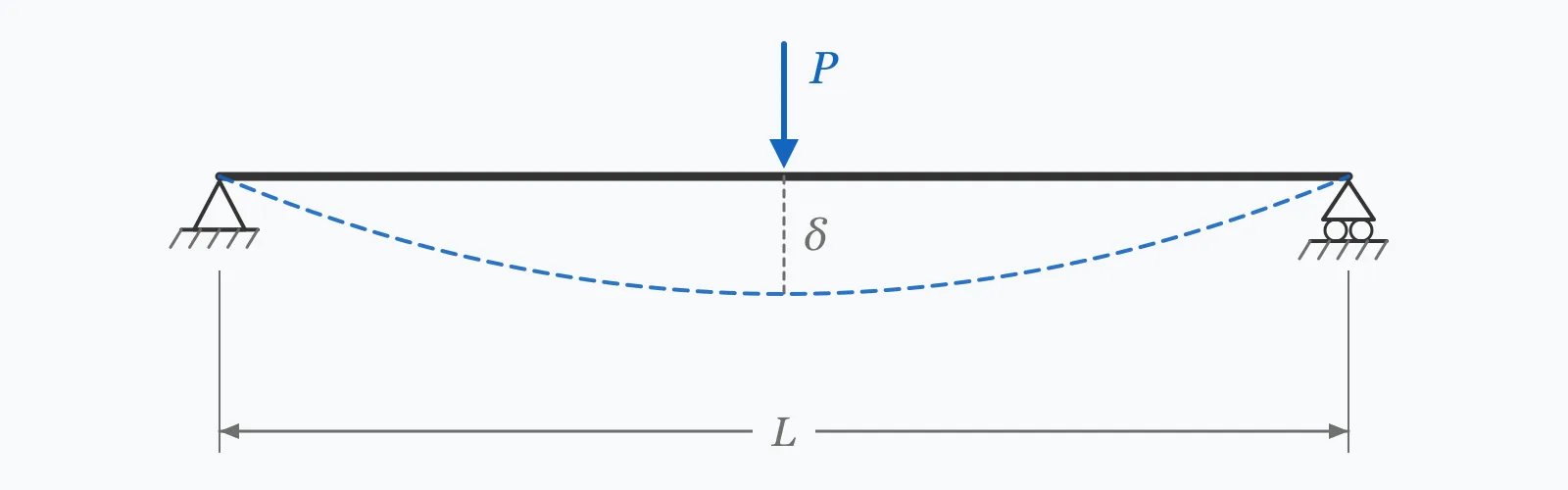
A simply supported beam with a point load at midspan deflects by δ = PL³/48EI. Enter the load, span, modulus of elasticity and moment of inertia, and this calculator returns the maximum deflection in millimetres, the span-to-deflection ratio, and whether the beam satisfies the L/360 limit used for floor members in IBC and most national codes.
Enter your values and press Calculate. You will get the maximum deflection at midspan, the span-to-deflection ratio (the form codes use), and the L/360 allowable value for comparison.
Step-by-Step Solution
Preliminary design aid. Results follow the published formulas cited
below and are intended for estimating, study and early design. Final design must be
verified by a licensed Professional Engineer against the code in force for your project.
Key Benefits
✓Returns maximum deflection, span-to-deflection ratio and the L/360 allowable in one pass
✓Shows every unit conversion and substitution, so the result can be checked by hand
✓Flags results that fail L/360 or fall below a span-to-deflection ratio of 180
✓Sensitivity chart shows how deflection responds across the full span range
✓Works in Metric (SI) and Imperial units with no re-entry
✓Results can be shared as a link, exported to CSV or printed as a calculation record
✓Formulas cited to AISC, IBC and Eurocode so the basis is auditable
What Is Beam Deflection?
Beam deflection is the vertical displacement of a beam's neutral axis away from its unloaded position. For a simply supported beam carrying a single concentrated load at midspan, the largest displacement occurs directly under the load, and its magnitude is given by the closed-form solution δ = PL³/48EI derived from Euler-Bernoulli beam theory. The four quantities in that expression are the only things that matter: how hard you push (P), how far apart the supports are (L), how stiff the material is (E), and how efficiently the cross-section distributes material away from the neutral axis (I).
Why deflection governs so many designs
Strength and stiffness scale differently. Bending stress in a simply supported beam under a midspan point load goes as PL/4 divided by the section modulus, so it is linear in span. Deflection goes as PL³, so it is cubic in span. As spans get longer, deflection overtakes stress as the binding constraint, which is why long-span floor beams are almost always sized by serviceability rather than by moment capacity. In steel floor framing beyond roughly 8 to 10 metres it is common for the chosen section to have two or three times the strength strictly required, purely to keep deflection and floor vibration acceptable.
Serviceability, not safety
Deflection limits protect function and appearance rather than structural integrity. The classic L/360 limit traces back to the deflection at which a plaster ceiling begins to crack, and it is applied to the live-load portion of deflection in IBC Table 1604.3. Limits are therefore conventions tied to what the beam supports: a roof with no ceiling below tolerates L/180, a floor with brittle finishes may demand L/480, and a beam supporting a masonry wall is often held to an absolute limit in millimetres regardless of span.
What this calculator assumes
The formula used here is exact for its own idealisation: a prismatic, homogeneous, linearly elastic beam, simply supported at both ends, loaded by a single concentrated force at midspan, with deflection small relative to span and shear deformation neglected. Real beams depart from this in ways that matter — partial end fixity reduces deflection, continuity over supports reduces it further, concrete cracks and creeps, and timber and composites carry meaningful shear deflection. The Limitations section below sets out when each departure becomes significant.
Formula
δ_max = PL³ / (48EI)
Maximum deflection at midspan of a simply supported beam under a concentrated load at midspan
Related Formulas
δ_max = 5wL⁴ / (384EI)
δ_max = PL³ / (3EI)
δ_max = PL³ / (192EI)
L / δ_max
Variable Definitions
Symbol
Variable
Unit
Description
δ_max
Maximum Deflection
mm
Largest vertical displacement of the beam, occurring at midspan for a symmetric point load.
P
Applied Load
kN
Concentrated force applied at midspan. Use the unfactored service load — deflection is a serviceability check, so load factors do not apply.
L
Span Length
m
Clear distance between support centrelines. Deflection varies with the cube of this value, making it the most sensitive input.
E
Modulus of Elasticity
GPa
Material stiffness. Structural steel is 200 GPa, aluminium 69 GPa, normalweight concrete 25–35 GPa, sawn softwood 9–11 GPa.
I
Moment of Inertia
×10⁶ mm⁴
Second moment of area about the bending axis. For a rectangle, I = bh³/12 — depth is cubed, so section depth dominates stiffness.
EI
Flexural Rigidity
kN·m²
The product that actually resists bending. Any combination of E and I giving the same EI produces the same deflection.
How to Use This Calculator
Enter the service load, not the factored loadDeflection is checked at service level. Use the unfactored load combination relevant to the limit you are checking — live load alone for the L/360 floor check, dead plus live for the L/240 total-load check.
Measure the span between support centrelinesFor a beam sitting on masonry or a wide bearing plate, use the centre-to-centre bearing distance rather than the clear opening. Because deflection scales with L³, a 5% error in span becomes a 16% error in deflection.
Enter the modulus of elasticity for your materialStructural steel is 200 GPa (29,000 ksi) regardless of grade — strength varies between grades, stiffness does not. For concrete use the secant modulus at the relevant age; for timber use the mean modulus E_mean for deflection, not the 5th-percentile value used for strength.
Look up the moment of inertia for your sectionTake I from the manufacturer's section tables about the axis you are bending about — usually I_x for a beam bending in its strong direction. For a plain rectangle, compute bh³/12. Enter it in units of ×10⁶ mm⁴.
Press Calculate and read the ratio, not just the millimetresThe span-to-deflection ratio is what codes are written in. A ratio above 360 satisfies the standard floor live-load limit; below 240 you are outside almost every general-purpose limit.
Use the chart to find the governing spanSweep the span to see where your section crosses the limit. This is usually more useful than a single answer, because it tells you how much margin the design has.
Save, share or export the calculationCopy a shareable link that reproduces your exact inputs, download a CSV of inputs, results and steps for a calculation file, or print the page as a PDF record.
Worked Examples
Example 1
A simply supported steel beam spans 6.0 m and carries a 10 kN service point load at midspan. The section has I_x = 33.4 ×10⁶ mm⁴ and is structural steel with E = 200 GPa. Check it against the L/360 floor limit.
Step-by-Step Solution
Convert to consistent units: P = 10 kN = 10,000 N; L = 6.0 m = 6,000 mm; E = 200 GPa = 200,000 MPa; I = 33.4 ×10⁶ = 33,400,000 mm⁴
Check: 6.74 mm ≤ 16.67 mm, and ratio 890 ≥ 360 — the beam passes with roughly 2.5× margin on deflection
Example 2
The same beam and the same load, but the span is increased from 6.0 m to 9.0 m — a 50% increase. This is the case that shows why span dominates every other variable.
Step-by-Step Solution
Only L changes: P = 10,000 N; L = 9,000 mm; E = 200,000 MPa; I = 33,400,000 mm⁴
Check: 22.74 mm ≤ 25.0 mm — it still passes, but the margin has collapsed from 2.5× to 1.10×
Note the scaling: span rose by a factor of 1.5 and deflection rose by 1.5³ = 3.375, from 6.74 mm to 22.74 mm. A further increase to 9.5 m would fail the L/360 check.
Example 3
A timber member for comparison: a 63 × 225 mm glulam joist spanning 4.2 m under a 3.5 kN point load at midspan, with E_mean = 11 GPa. Timber's low modulus is offset by using a deep rectangular section.
Step-by-Step Solution
Moment of inertia of the rectangle: I = bh³/12 = 63 × 225³ / 12 = 63 × 11,390,625 / 12 = 59.8 ×10⁶ mm⁴
Convert: P = 3,500 N; L = 4,200 mm; E = 11 GPa = 11,000 MPa; I = 59,800,000 mm⁴
Allowable at L/360: 4,200 / 360 = 11.67 mm — the joist passes
Caution: this is the instantaneous elastic deflection only. Timber creeps under sustained load, and Eurocode 5 applies a deformation factor k_def to the permanent portion, which can increase the long-term value by more than half.
Span Sensitivity
Deflection grows with the cube of span, so the curve steepens rapidly to the right. Sweep the span from 1 to 15 metres while holding your load, modulus and section constant to see where your beam stops satisfying its serviceability limit. The marker shows your current span.
Maximum Deflection vs Span Length (L)
Recomputed live from your inputs. The marker shows your current value.
Line chart of Maximum Deflection against Span Length (L). The same
values are listed in the data table below.
Values plotted above, sampled across the span length (l) range.
How to Interpret Your Results
Codes express deflection limits as a fraction of span, so the span-to-deflection ratio is the number to read first. A higher ratio means a stiffer beam. The bands below are the conventional thresholds for building members; your project's governing code, or a brittle finish, may impose something stricter.
Span / Deflection Ratio: ≥ 480Stiff enough for brittle finishes
A span-to-deflection ratio of your result exceeds L/480, the limit normally applied where deflection would damage brittle finishes such as plaster, stone cladding or glazing. This beam satisfies every ordinary building limit with margin to spare.
Span / Deflection Ratio: 360 – 480Satisfies the standard L/360 floor limit
A span-to-deflection ratio of your result meets the L/360 live-load limit that IBC Table 1604.3 applies to floor members supporting plaster ceilings. It falls short of the stricter L/480 sometimes required beneath brittle finishes.
Span / Deflection Ratio: 240 – 360Meets L/240 but fails the L/360 floor limit
A span-to-deflection ratio of your result satisfies the L/240 total-load limit but not the L/360 live-load limit for floors. This may be acceptable for a roof member or a beam with no ceiling below; for a floor with finishes, increase the section depth or reduce the span.
Span / Deflection Ratio: 180 – 240Below general building limits
A span-to-deflection ratio of your result falls below the L/240 limit that applies to most building members. Only lightly-serviced roof members with no ceiling are normally permitted this much movement. Revisit the section before proceeding.
Span / Deflection Ratio: < 180Exceeds every ordinary deflection limit
A span-to-deflection ratio of your result is below L/180, the most permissive limit in general building use. Deflection of this magnitude is visible to occupants, will disturb finishes and can pond water on a flat roof. A deeper section, an added support, or a shorter span is required.
Maximum Deflection: ≥ 100Large-displacement territory
An absolute deflection of your result mm is large enough that the small-deflection assumption behind this formula begins to lose accuracy, and that an absolute limit — many codes cap deflection beneath masonry walls at 12–20 mm regardless of span — is likely to govern before the ratio does.
Common Mistakes to Avoid
Using factored (ultimate) loads instead of service loads
Why it matters:Deflection is a serviceability limit state. Feeding in loads multiplied by 1.2 or 1.6 overstates deflection by that same factor and can lead you to oversize a beam that was already compliant.
✓How to avoid it:Use unfactored service loads. Check the live-load portion alone against L/360, and dead plus live against L/240.
Assuming a higher steel grade will reduce deflection
Why it matters:Every structural steel grade has essentially the same modulus of elasticity, 200 GPa. Specifying S460 instead of S275 raises strength by two thirds and changes deflection by nothing at all.
✓How to avoid it:To reduce deflection, increase I — usually by increasing section depth — or reduce the span. Grade only helps when strength governs.
Mixing unit systems inside the formula
Why it matters:Substituting span in metres alongside I in mm⁴ and E in MPa yields an answer wrong by a factor of 10⁹. It is by far the most common arithmetic failure in hand deflection checks.
✓How to avoid it:Convert everything to N, mm and MPa before substituting, exactly as the step-by-step solution above does. The calculator shows each conversion so it can be checked.
Applying the midspan point-load formula to a distributed load
Why it matters:PL³/48EI and 5wL⁴/384EI are different problems. Treating a uniform load as an equivalent point load at midspan overestimates deflection by about 60%.
✓How to avoid it:Use 5wL⁴/384EI for a uniformly distributed load. Where both act, compute each separately and add them — superposition is valid in the linear elastic range.
Using gross moment of inertia for a reinforced concrete beam
Why it matters:Once a concrete beam cracks in the tension zone, its effective stiffness drops sharply. Using I_g can underestimate real deflection by a factor of two or three.
✓How to avoid it:Use the effective moment of inertia I_e from ACI 318-19 §24.2.3, and apply the long-term multiplier for creep and shrinkage. This calculator's elastic result is only the instantaneous, uncracked value.
Ignoring shear deflection in deep or timber beams
Why it matters:Euler-Bernoulli theory neglects shear deformation entirely. In beams with a span-to-depth ratio below about 10, and in materials with a low shear-to-elastic modulus ratio such as timber and composites, the shear component can add 5–15% to total deflection.
✓How to avoid it:For span-to-depth ratios under 10, use Timoshenko beam theory or add the shear term explicitly. For timber, follow the shear-inclusive provisions of Eurocode 5 or the NDS.
Forgetting that real end conditions are rarely pinned
Why it matters:A beam bolted through a substantial end plate has partial rotational restraint, which reduces deflection below the simply supported value — sometimes by 20–30%. Assuming pinned ends is conservative for deflection but can mislead on end moments.
✓How to avoid it:Treat the simply supported result as an upper bound. Where continuity is genuine and detailed for, model the real end fixity rather than claiming the benefit informally.
Checking deflection but not vibration
Why it matters:Long-span floors that satisfy L/360 can still be unacceptably lively. Occupant complaints about bouncy floors are usually a natural-frequency problem, not a static deflection problem.
✓How to avoid it:For floor spans beyond roughly 8 m, follow a dedicated vibration procedure such as AISC Design Guide 11 in addition to the static check.
Practical Applications
▸Sizing steel floor beams where serviceability governs over bending capacity
▸Checking timber joists and rafters against span tables during residential design
▸Verifying that crane runway and monorail beams stay within their deflection tolerance
▸Estimating the precamber required in long-span fabricated girders
▸Assessing whether an existing beam can carry a new plant load without excessive sag
▸Checking lintel deflection beneath masonry, where cracking limits govern
▸Confirming formwork and falsework stiffness before a concrete pour
▸Preliminary sizing of temporary works, needle beams and shoring
Industry Use Cases
Commercial steel-frame construction
For open-plan office floors spanning 9 to 12 m, the beam that satisfies bending capacity is usually two or three serial sizes lighter than the beam that satisfies L/360. Engineers run the deflection check first and treat the resulting section as the starting point, then verify capacity — the reverse of the usual order.
Residential timber framing
Span tables published by timber associations are generated by inverting this calculation across every combination of section, spacing and load. A designer verifying a non-standard case — an unusual load, a species outside the table, a member notched at bearing — falls back to the closed-form check.
Industrial and plant engineering
Equipment support beams frequently have deflection limits set by the machine vendor rather than by building code — a limit such as L/750 or an absolute 3 mm, imposed to protect shaft alignment. These vendor limits usually govern the design entirely.
Bridge and infrastructure engineering
Pedestrian bridge decks are governed by comfort rather than strength. Deflection is checked as a first pass, then followed by a dynamic assessment, since a footbridge satisfying static limits can still be unacceptable under crowd-induced vibration.
Temporary works and formwork
Formwork deflection becomes a permanent surface defect in the finished concrete. Soffit formwork bearers are usually held to L/270 or an absolute 3 mm, whichever is smaller, and are checked against the wet concrete load rather than the service load.
Building assessment and retrofit
When a building changes use — an office floor becoming a library or archive — the imposed load can double. A quick deflection check across the existing beam sizes identifies which members need strengthening before a full analysis is commissioned.
Expert Tips
💡Depth beats everything else: for a rectangular section I = bh³/12, so doubling the depth increases stiffness eightfold while doubling the width only doubles it.
💡Compare EI rather than sections when weighing materials. A glulam beam with three times the I of a steel beam at one-eighteenth the modulus is still six times more flexible.
💡Check the ratio, not the millimetres, when scanning a schedule of beams — the ratio is directly comparable against the code limit whatever the span.
💡Precamber long-span beams by roughly the dead-load deflection so the member sits level under permanent load; specify the camber on the drawing, not just in the calculation.
💡For continuous beams over several supports, midspan deflection is typically 20–40% lower than the simply supported value. Using this calculator on a continuous beam is safe but wasteful.
💡When a beam fails deflection by a small margin, adding an intermediate support is far more effective than upsizing: halving the span cuts deflection to one-eighth at constant load.
💡Superpose load cases rather than combining them into one equivalent load — the linear elastic solutions add directly, and it keeps each contribution visible.
💡Record the assumed end conditions alongside the result. Most disputes about deflection calculations turn out to be disagreements about whether the ends were pinned or fixed.
Advantages & Limitations
Advantages
✓Closed-form and exact for its idealisation — no iteration, meshing or software licence
✓Requires only four inputs, all of them available from section tables and drawings
✓Provides an immediate upper bound: real end restraint only makes the beam stiffer
✓Transparent enough to be checked by hand and defended in a design review
✓The same expression underlies published span tables, so results are directly comparable
✓Superposition allows several load cases to be combined by simple addition
Limitations
!Valid only for a simply supported, prismatic, homogeneous, linearly elastic beam
!Neglects shear deformation — significant when span-to-depth falls below about 10, and in timber or composites
!Assumes a single concentrated load precisely at midspan; off-centre loads need the general expression
!Takes no account of concrete cracking, creep, shrinkage or timber creep, all of which increase long-term deflection
!Ignores lateral-torsional buckling and any second-order effect; this is a serviceability check only
!Says nothing about floor vibration, which frequently governs long-span floors that satisfy static limits
!Assumes deflection is small relative to span, so it loses accuracy in very flexible members
!Does not model composite action between a beam and a slab cast against it, which can substantially increase real stiffness
Deflection Formulas by Support and Load Case
The coefficient in the denominator is the whole story. All cases below share the same PL³/EI or wL⁴/EI structure, so relative stiffness can be read directly from the coefficient — a fixed-fixed beam is four times stiffer than a simply supported one under the same midspan point load.
Standard elastic deflection cases for prismatic beams. Relative values assume identical span, section and total applied load.
For a simply supported beam with a concentrated load at midspan, the maximum deflection is δ = PL³/48EI, occurring directly under the load. P is the applied load, L the span, E the modulus of elasticity and I the moment of inertia. For a uniformly distributed load the formula becomes δ = 5wL⁴/384EI.
What is an acceptable deflection for a beam?
The usual limit for floor members is L/360 under live load, meaning a 6 m span may deflect no more than 16.7 mm. IBC Table 1604.3 also gives L/240 for total load and L/180 for roof members without ceilings. Brittle finishes such as plaster or stone cladding often call for L/480 or stricter.
Why is L/360 the standard deflection limit?
The value originates from the deflection at which a plaster ceiling attached to the underside of a floor begins to crack. It has been carried into modern codes as a general serviceability convention for floors, even where plaster is no longer used, because it reliably produces floors that feel solid and keep their finishes intact.
Does using stronger steel reduce deflection?
No. All structural steel grades share a modulus of elasticity of about 200 GPa, and deflection depends on stiffness rather than strength. Switching from S275 to S460 raises capacity substantially and changes deflection not at all. To reduce deflection you must increase the moment of inertia — normally by using a deeper section — or shorten the span.
How does span length affect deflection?
Deflection scales with the cube of span under a point load and the fourth power under a distributed load. Doubling a span multiplies point-load deflection by eight at constant load. This is why span is almost always the dominant variable and why adding an intermediate support is far more effective than upsizing the section.
Should I use factored or unfactored loads for a deflection check?
Unfactored service loads. Deflection is a serviceability limit state, so the load factors used for strength design do not apply. Check the live-load component alone against L/360 and the dead-plus-live combination against L/240.
What is the difference between deflection and deformation?
Deflection specifically means displacement perpendicular to a member's original axis — the sag of a beam. Deformation is the general term covering any change in shape, including axial shortening, twist and shear distortion. Every deflection is a deformation, but not the reverse.
How do I calculate the moment of inertia for my beam?
For a solid rectangle, I = bh³/12 where b is width and h is depth. For rolled steel sections, read I_x or I_y directly from the manufacturer's or standards body's section tables. For built-up and composite shapes, use the parallel axis theorem to combine the parts about the common neutral axis.
Does this calculator work for cantilever beams?
No. A cantilever with a point load at its free end deflects by PL³/3EI, sixteen times the simply supported value for the same load and span. Using the simply supported formula on a cantilever would understate deflection dramatically. Use the cantilever expression listed in the Related Formulas section.
Why does my real beam deflect less than this calculation predicts?
Almost always because the real end connections provide some rotational restraint, whereas the formula assumes ideal pins. Composite action with a slab cast against the beam, and contributions from non-structural elements, add further stiffness. The simply supported result is therefore an upper bound, which is the conservative direction for a serviceability check.
How much does concrete creep add to deflection?
A great deal. ACI 318 applies a long-term multiplier to the sustained-load portion of instantaneous deflection, reaching 2.0 at five years for a beam with no compression reinforcement. Combined with cracking, total long-term deflection in a reinforced concrete beam commonly reaches three to four times the elastic value this calculator returns.
When does shear deflection need to be included?
When the span-to-depth ratio drops below roughly 10, or when the material has a low shear modulus relative to its elastic modulus — timber, plywood webs and fibre composites in particular. In those cases shear can contribute 5 to 15% of total deflection, and Timoshenko beam theory should be used instead of Euler-Bernoulli.
What deflection limit applies to a beam supporting a masonry wall?
Masonry is brittle and intolerant of movement, so limits are stricter than for ordinary floors and are frequently absolute rather than span-based. A common requirement is L/600 or 12 mm, whichever is smaller, measured under the load applied after the masonry is built. Check the masonry code in force for your project.
Can I add deflections from different loads together?
Yes, provided the beam stays within its linear elastic range, which is the normal service condition. Superposition lets you compute deflection for each load case separately and sum the results — a point load plus a distributed load, for instance. Keeping the contributions separate also makes the calculation easier to review.
Glossary
Deflection
The displacement of a point on a beam measured perpendicular to its original longitudinal axis, normally reported as the maximum value along the span.
Serviceability limit state
A design condition concerning function, comfort and appearance rather than collapse. Deflection, vibration and cracking are serviceability checks, assessed at unfactored service loads.
Span-to-deflection ratio
Span divided by maximum deflection, written L/δ. A dimensionless measure of stiffness that allows beams of different spans to be compared against the same code limit.
Modulus of elasticity (E)
The ratio of stress to strain in the elastic range, also called Young's modulus. A material property independent of section geometry; about 200 GPa for all structural steels.
Moment of inertia (I)
The second moment of area of a cross-section about its bending axis, quantifying how efficiently material is distributed away from the neutral axis.
Flexural rigidity (EI)
The product of modulus of elasticity and moment of inertia. The single quantity that governs elastic deflection — equal EI means equal deflection, whatever the material.
Euler-Bernoulli beam theory
The classical beam theory assuming plane sections remain plane and perpendicular to the neutral axis, which neglects shear deformation. Accurate for slender beams.
Timoshenko beam theory
An extension of Euler-Bernoulli theory that includes shear deformation and rotary inertia, required for deep beams and low-shear-modulus materials.
Simply supported
A beam resting on a pin at one end and a roller at the other, free to rotate at both supports and carrying no end moment.
Precamber
A deliberate upward curvature fabricated into a beam so that it deflects to a level position under permanent load.
Superposition
The principle that responses to individual loads may be added, valid while the structure remains linear and elastic.
Effective moment of inertia (Ie)
A reduced stiffness used for reinforced concrete that accounts for partial cracking along the span, defined in ACI 318-19 §24.2.3.
Scientific & Standards References
AISC Steel Construction Manual, 16th Edition — Beam Diagrams and Formulas (Part 3) — American Institute of Steel Construction
AISC Design Guide 3: Serviceability Design Considerations for Steel Buildings, 2nd Edition — American Institute of Steel Construction
AISC Design Guide 11: Vibrations of Steel-Framed Structural Systems Due to Human Activity, 2nd Edition — American Institute of Steel Construction
International Building Code, Table 1604.3 — Deflection Limits — International Code Council
EN 1993-1-1 §7.2 — Serviceability limit states for steel structures — CEN
EN 1990 Annex A1.4 — Serviceability limit states and deflection criteria — CEN
ACI 318-19 §24.2 — Deflections of reinforced concrete members — American Concrete Institute
Gere, J. M. & Goodno, B. J., Mechanics of Materials, 9th Edition — Chapter 9: Deflections of Beams — Cengage Learning
Roark's Formulas for Stress and Strain, 9th Edition — Table 8.1: Shear, Moment, Slope and Deflection Formulas for Elastic Straight Beams — McGraw-Hill
Conclusion
Maximum deflection of a simply supported beam under a midspan point load follows δ = PL³/48EI, and the span-to-deflection ratio it produces is what code limits are written against — L/360 for floor members under live load, L/240 for total load, stricter where brittle finishes are involved. Because deflection scales with the cube of span while bending stress scales linearly, serviceability rather than strength governs most long-span designs, and increasing section depth or reducing span is far more effective than specifying a stronger grade of steel. Treat the result as an upper bound: real end restraint, continuity and composite action all make a built beam stiffer than this idealisation, while concrete cracking and creep, timber creep and shear deformation push long-term deflection the other way.
Run your own numbers above, then use the span sensitivity chart to see how much margin the design actually has before it crosses its limit.