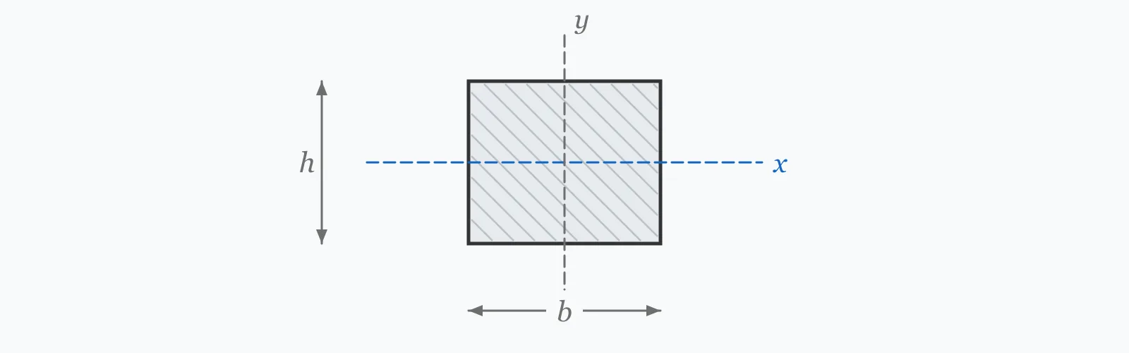
Section modulus converts a bending moment into a stress. For a rectangle, the elastic modulus is S = bh²/6 and the plastic modulus is Z = bh²/4. Enter width and depth to get both. Which one you use depends on the design method: elastic for allowable-stress and serviceability checks, plastic for limit-state capacity in a compact section.
Calculator
Units:
mm
Dimension perpendicular to the applied load
mm
Dimension parallel to the load — squared in the formula
Calculation Result
Press Calculate to get both the elastic modulus S and the plastic modulus Z. Their ratio is the shape factor — 1.5 for any rectangle — which tells you how much reserve exists between first yield and full plastification.
Step-by-Step Solution
Preliminary design aid. Results follow the published formulas cited
below and are intended for estimating, study and early design. Final design must be
verified by a licensed Professional Engineer against the code in force for your project.
Key Benefits
✓Returns elastic and plastic section modulus together, so neither is used by mistake
✓Makes the 1.5 shape factor of a rectangle explicit rather than implicit
✓Directly feeds the bending stress check σ = M/S and the capacity check Mp = Fy·Z
✓Shows the substitution so the result can be reproduced by hand
✓Sensitivity chart makes the quadratic effect of depth immediately visible
✓Shareable links and CSV export for calculation records
What Is Section Modulus?
Section modulus is the geometric property that relates bending moment to bending stress. The elastic value is defined as S = I/c, the moment of inertia divided by the distance from the neutral axis to the extreme fibre. For a rectangle, substituting I = bh³/12 and c = h/2 gives S = bh²/6. Bending stress then follows directly as σ = M/S, and the section reaches first yield when that stress equals the material's yield strength.
Elastic versus plastic
First yield is not failure. Once the extreme fibres yield, they continue to carry stress while the yielded zone spreads inward, until the entire section has plastified and a plastic hinge forms. The plastic section modulus Z is the property describing that fully-yielded state, defined as the first moment of area of the two halves about the plastic neutral axis. For a rectangle it works out to bh²/4, and the plastic moment is Mp = Fy·Z.
The shape factor
The ratio Z/S is called the shape factor, and it measures the reserve between first yield and full plastification. Every rectangle has a shape factor of exactly 1.5, meaning a rectangular section carries half again as much moment after first yield as it did at first yield. An I-section, with most of its material already near the extreme fibres, has far less to gain — typically 1.12 to 1.18 — because the flanges yield almost simultaneously.
Formula
S = bh² / 6
Elastic section modulus of a rectangle about its horizontal centroidal axis
Related Formulas
Z = bh² / 4
S = I / c
σ = M / S
M_p = F_y · Z
Variable Definitions
Symbol
Variable
Unit
Description
S
Elastic Section Modulus
mm³
Relates moment to extreme-fibre stress. Governs allowable-stress design and any check limited to first yield.
Z
Plastic Section Modulus
mm³
Relates yield strength to the fully-plastic moment. Used in limit-state design of compact sections.
b
Width
mm
Horizontal dimension, perpendicular to the applied load.
h
Height (Depth)
mm
Vertical dimension, parallel to the load. Squared in both expressions.
c
Extreme Fibre Distance
mm
Distance from the neutral axis to the outermost fibre — h/2 for a symmetric rectangle.
Z/S
Shape Factor
—
Reserve between first yield and full plastification. Exactly 1.5 for any rectangle.
How to Use This Calculator
Confirm which modulus your design method needsAllowable-stress design and serviceability checks use the elastic modulus S. Limit-state design of a compact section — LRFD in AISC, or Class 1 and 2 sections in Eurocode 3 — uses the plastic modulus Z.
Enter the dimensions in the loaded orientationDepth is the dimension parallel to the load. Because it is squared, transposing width and depth on a 100 × 200 section changes the result by a factor of four.
Check the bending stressDivide the applied service moment by S to obtain the extreme-fibre stress, then compare it against the allowable stress for your material. Keep units consistent: a moment in kN·m must be converted to N·mm before dividing by a modulus in mm³.
Or check the plastic capacityMultiply Z by the yield strength to get the plastic moment Mp, then apply the resistance factor — 0.90 in AISC LRFD — before comparing against the factored moment.
Verify the section is compact before using ZThe plastic modulus is only achievable if the section can reach full plastification without local buckling. Slender webs or flanges buckle first, and such sections must be designed on the elastic modulus instead.
Worked Examples
Example 1
A rectangular section is 100 mm wide and 200 mm deep. Find both section moduli, then check the bending stress under a 25 kN·m service moment.
Check: 37.5 MPa is comfortably below the yield strength of any structural steel, so the section stays elastic under this moment.
Example 2
The same section, now checked for plastic moment capacity in 355 MPa steel, and compared against the moment that causes first yield. This is where the shape factor becomes money.
Step-by-Step Solution
First-yield moment: My = Fy × S = 355 × 666,667 = 236,666,785 N·mm = 236.7 kN·m
Design capacity if the section were non-compact and limited to first yield: 0.90 × 236.7 = 213.0 kN·m
The comparison is the practical point: being able to use the plastic modulus raises usable capacity from 213 to 320 kN·m — a 50% gain from geometry alone, with no change in material or dimensions.
Depth Sensitivity
Both moduli grow with the square of depth, so the two curves keep a constant 1.5 ratio while rising steeply. Switch between S and Z to compare, and note that the gap between them widens in absolute terms even though the shape factor never changes. The marker shows your current depth.
Elastic Modulus (S) vs Height (h)
Recomputed live from your inputs. The marker shows your current value.
Line chart of Elastic Modulus (S) against Height (h). The same
values are listed in the data table below.
Values plotted above, sampled across the height (h) range.
How to Interpret Your Results
Section modulus is a geometric property with no pass-or-fail threshold of its own; it becomes a check only once you pair it with a moment or a yield strength. The bands below relate the computed value to the member sizes it typically corresponds to.
Elastic Modulus (S): < 50000Light-duty section
An elastic modulus of your result mm³ corresponds to a small member — light framing, secondary supports or bracing. At 355 MPa, first yield occurs at roughly S × 355 N·mm, so confirm the applied moment is well inside that.
Elastic Modulus (S): 50000 – 2000000Typical structural range
An elastic modulus of your result mm³ sits in the normal range for beams and joists in buildings. Divide your service moment by this value to obtain the extreme-fibre stress and compare it against the allowable stress.
Elastic Modulus (S): ≥ 2000000Heavy section
An elastic modulus of your result mm³ indicates a large member — a transfer beam, crane girder or long-span primary element. At this scale, deflection and lateral-torsional buckling usually govern the design before bending stress does.
Common Mistakes to Avoid
Using the plastic modulus for a non-compact section
Why it matters:Z assumes the section can fully plastify. A slender flange or web buckles locally first, so the member never reaches Mp and the calculated capacity is unconservative.
✓How to avoid it:Check the width-to-thickness ratios against the compactness limits in AISC 360 Table B4.1b, or the Class 1 and 2 limits in Eurocode 3, before using Z.
Confusing section modulus with moment of inertia
Why it matters:They have different units and different jobs: I is in mm⁴ and governs deflection, S is in mm³ and governs stress. Substituting one for the other produces an error of the order of the section depth.
✓How to avoid it:Remember S = I/c. Use I for stiffness questions and S for strength questions.
Mixing kN·m with mm³
Why it matters:Dividing a moment in kN·m by a modulus in mm³ gives a number a million times too small, which usually looks plausible enough to pass unnoticed.
✓How to avoid it:Convert the moment to N·mm first — multiply kN·m by 10⁶ — so that the result comes out directly in MPa.
Using the elastic modulus about the wrong axis
Why it matters:A rectangle bent about its weak axis has a section modulus smaller by a factor of h/b. For a 100 × 300 section that is a factor of three.
✓How to avoid it:Match the axis to the loading direction. Depth is always measured parallel to the applied load.
Assuming a shape factor of 1.5 for every section
Why it matters:1.5 is specific to rectangles. An I-section is around 1.12 to 1.18, a solid circle is 1.70, and a circular tube around 1.27. Applying 1.5 universally overstates the reserve of a wide-flange beam by a third.
✓How to avoid it:Take Z directly from section tables rather than scaling S, and reserve the 1.5 factor for genuinely rectangular members.
Practical Applications
▸Checking bending stress in beams under service loads
▸Determining plastic moment capacity for limit-state design
▸Sizing timber joists and rafters, which are usually plain rectangles
▸Selecting steel sections from tables by required modulus
▸Verifying capacity of welded plate girders and built-up members
▸Assessing residual capacity of a corroded or notched member
Industry Use Cases
Steel building design
Section selection normally starts from a required Z: divide the factored moment by 0.9·Fy, then pick the lightest section in the tables that exceeds it. The calculated value becomes the entry point into the section catalogue.
Timber engineering
Timber is designed elastically because it has no ductile plateau, so only S is used. Sawn sections are plain rectangles, making bh²/6 the direct route from a required capacity to a required depth.
Structural assessment
When a member has lost section to corrosion, engineers recompute S from measured remaining dimensions. Because depth is squared, a uniform loss reduces capacity far more than it reduces weight, which is often the finding that triggers strengthening.
Expert Tips
💡Doubling depth quadruples both moduli; doubling width only doubles them. Depth is the efficient dimension.
💡For a rectangle, Z is always exactly 1.5 × S — a fast sanity check on any computed pair.
💡To size a section, invert the problem: required S = M/σ_allowable, then solve h = √(6S/b).
💡Section modulus already contains the extreme-fibre distance, which is why it maps directly to stress while I does not.
💡For an unsymmetric section there are two elastic moduli, one for each face; design against the smaller.
💡Confirm compactness before claiming the plastic modulus — the 50% gain evaporates if the flange buckles first.
Advantages & Limitations
Advantages
✓Converts a bending moment directly into a stress in one step
✓Both elastic and plastic values follow from the same two dimensions
✓Independent of material, so one result serves steel, timber and concrete alike
✓Directly invertible for sizing, letting a required modulus drive section selection
✓Simple enough to check by hand during a design review
Limitations
!Covers rectangular sections only; tees, angles and channels need their own derivation
!Assumes a symmetric section, so the single elastic value applies to both faces
!The plastic modulus is unusable unless the section is compact enough to avoid local buckling
!Says nothing about lateral-torsional buckling, which often governs long unbraced beams
!Gives gross properties, ignoring holes, notches and net-section loss
!Not applicable to reinforced concrete, which requires a transformed cracked section
Section Modulus and Shape Factor by Shape
The shape factor is the reserve between first yield and full plastification. Shapes that already concentrate material at the extreme fibres have less left to gain, which is why an efficient elastic section is a poor plastic performer in relative terms.
Shape factors for common cross-sections. Values for rolled shapes vary with the flange-to-web area ratio and should be taken from section tables.
It is the geometric property relating bending moment to bending stress, defined elastically as S = I/c. Dividing an applied moment by S gives the stress at the extreme fibre. For a rectangle, S = bh²/6.
What is the difference between elastic and plastic section modulus?
The elastic modulus S corresponds to first yield at the extreme fibre, while the plastic modulus Z corresponds to the whole section having yielded. Z is always larger, and their ratio is the shape factor — exactly 1.5 for a rectangle.
When should I use Z instead of S?
Use Z in limit-state design when the section is compact enough to plastify without local buckling — AISC LRFD, or Class 1 and 2 sections in Eurocode 3. Use S for allowable-stress design, for non-compact sections, and for materials such as timber that lack a ductile plateau.
What is the shape factor?
The ratio Z/S, measuring reserve capacity between first yield and full plastification. It is 1.5 for a rectangle, about 1.70 for a solid circle, and only 1.12 to 1.18 for a wide-flange section bent about its strong axis.
How do I calculate bending stress from section modulus?
Divide the bending moment by the section modulus: σ = M/S. Convert the moment to N·mm and use a modulus in mm³ so the answer comes out in MPa directly. A 25 kN·m moment on a 666,667 mm³ section gives 37.5 MPa.
How do I find the required section modulus?
Rearrange the stress equation: required S = M/σ_allowable. For plastic design, required Z = Mu/(ϕ·Fy). The result is what you take into the section tables to choose the lightest adequate member.
Why is the plastic modulus larger than the elastic one?
Elastic behaviour assumes stress varies linearly from zero at the neutral axis, so inner fibres are under-used. In the fully plastic state every fibre carries yield stress, so the same area resists a larger moment. For a rectangle that gain is exactly 50%.
Is section modulus the same as moment of inertia?
No. Moment of inertia is in mm⁴ and governs stiffness and deflection; section modulus is in mm³ and governs stress and strength. They are related by S = I/c, where c is the distance from the neutral axis to the extreme fibre.
Does section modulus depend on the material?
No, it is purely geometric. Material enters when you compare the resulting stress to an allowable value, or when you multiply Z by a yield strength to obtain a plastic moment.
What happens to section modulus if a beam corrodes?
It falls faster than the weight does, because depth is squared. A rectangular member losing 10% of its depth retains only 0.9² = 81% of its modulus, so uniform section loss is disproportionately damaging to capacity.
Glossary
Elastic section modulus (S)
I divided by the distance to the extreme fibre; relates moment to first-yield stress.
Plastic section modulus (Z)
The first moment of area of the two halves of a section about the plastic neutral axis; relates yield strength to the fully-plastic moment.
Shape factor
The ratio Z/S, quantifying reserve capacity between first yield and full plastification.
Plastic hinge
A location where a section has fully yielded and rotates at constant moment, allowing redistribution in a redundant structure.
Compact section
A section whose element slenderness allows full plastification before local buckling, making the plastic modulus usable.
Extreme fibre
The material furthest from the neutral axis, where bending stress reaches its maximum.
First yield moment (My)
The moment Fy·S at which the extreme fibre first reaches yield stress.
Plastic moment (Mp)
The moment Fy·Z at which the entire cross-section has yielded.
Local buckling
Buckling of an individual plate element such as a flange or web, which can prevent a section from reaching its plastic moment.
Scientific & Standards References
AISC 360-22 §F2 — Doubly Symmetric Compact I-Shaped Members Bent About Their Major Axis — American Institute of Steel Construction
AISC 360-22 Table B4.1b — Width-to-Thickness Ratios for Compression Elements in Flexure — American Institute of Steel Construction
EN 1993-1-1 §5.5 and §6.2.5 — Cross-section classification and bending resistance — CEN
Gere, J. M. & Goodno, B. J., Mechanics of Materials, 9th Edition — Chapter 5: Stresses in Beams — Cengage Learning
Roark's Formulas for Stress and Strain, 9th Edition — Table A.1: Properties of Sections — McGraw-Hill
Conclusion
Section modulus is the bridge between a bending moment and a stress, and between a yield strength and a moment capacity. The elastic value S = bh²/6 marks first yield; the plastic value Z = bh²/4 marks full plastification, and for a rectangle the reserve between them is exactly 50%. Which one applies is decided by the design method and by whether the section is compact enough to plastify without buckling locally — a check worth making before claiming the plastic capacity, because that is where the 50% either exists or does not.
Enter your own dimensions above, then sweep the depth in the chart to see how quickly capacity grows with section depth.