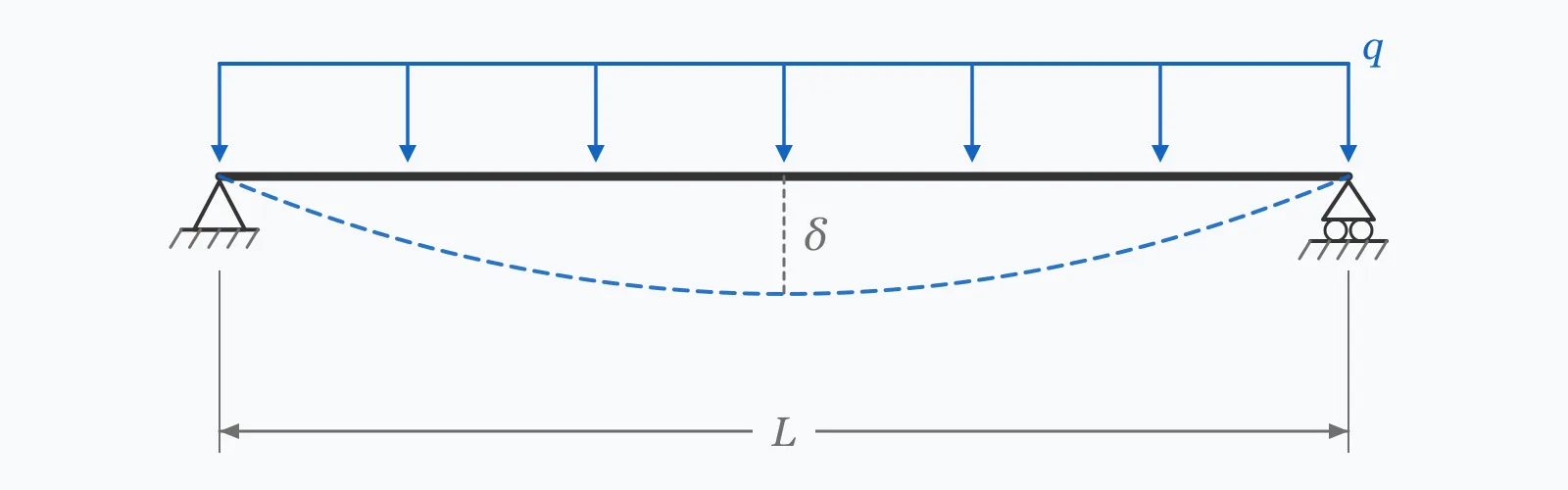
A timber joist's span is limited by two things: bending stress and deflection. This calculator works out both — the bending span from L = √(8·Fb·S/w) and the deflection span from L³ = 384·E·I/(1800·w) — and reports the smaller. The two limits sit close together for ordinary timber, so which one binds depends on the load and the allowable stress rather than on the section size.
Calculator
Units:
mm
38 mm and 47 mm are the standard regularised widths
mm
Standard depths: 145, 170, 184, 195, 220, 235 mm
mm
Centre-to-centre spacing; 400 and 600 mm are standard
kPa
Dead plus imposed. Domestic floor ≈ 2.0–2.5 kPa
MPa
After modification factors. C16 ≈ 4.5, C24 ≈ 6.0 MPa
MPa
Mean value: C16 ≈ 8,000, C24 ≈ 9,500 MPa
Calculation Result
Press Calculate for the maximum span allowed by bending, the maximum allowed by the L/360 deflection limit, and the governing value. The two are usually within 10% of each other, so it is worth seeing both rather than the governing figure alone.
Step-by-Step Solution
Preliminary design aid. Results follow the published formulas cited
below and are intended for estimating, study and early design. Final design must be
verified by a licensed Professional Engineer against the code in force for your project.
Key Benefits
✓Checks bending and deflection separately, then reports which one governs
✓Shows both limits side by side, so the margin between them is visible
✓Works for any rectangular section, not just tabulated sizes
✓Handles non-standard spacings and loads that published tables do not cover
✓Sensitivity chart shows how span responds to depth across the full range
✓Shareable links and CSV export for design records
What Is Wood Joist Span?
A floor joist is a simply supported beam carrying a strip of floor equal to its spacing. Converting the floor load in kilopascals to a line load on one joist is simply load times spacing: a 2.4 kPa floor with joists at 400 mm centres puts 0.96 kN/m on each joist. From there, two independent limits apply. The bending limit comes from setting the midspan moment wL²/8 equal to the allowable moment Fb·S, giving L = √(8·Fb·S/w). The deflection limit comes from setting 5wL⁴/(384EI) equal to L/360, giving L³ = 384EI/(1800w).
Which limit governs, and what changes it
The two limits scale differently with load: the bending span goes as one over the square root of load, the deflection span as one over its cube root. Heavier loads therefore erode the bending span faster, and at typical domestic loading with C24 properties bending governs by a narrow margin — 4.18 m against 4.43 m for a 38 × 235 joist. Drop the load below roughly 1.8 kPa, or raise the allowable stress above about 6.8 MPa, and deflection takes over. Real design pushes further towards deflection than this simplified check does, because codes add creep and often apply a stricter limit than L/360.
Depth beats everything else
Section modulus goes as bh²/6 and moment of inertia as bh³/12, so depth enters the bending limit squared and the deflection limit cubed. The net effect on span is the same in both: bending span goes as the square root of h², and deflection span as the cube root of h³, so each is simply proportional to depth. Increasing a joist from 184 mm to 235 mm — one standard size up, a 28% increase — raises the governing span by exactly 28%, from 3.27 m to 4.18 m. Widening the joist instead gives only the square root or cube root of the same ratio, which is why joists are deep and narrow.
Formula
L_max = min(L_bending, L_deflection)
Maximum joist span is the lesser of the bending and deflection limits
Related Formulas
L_bending = √(8 · F_b · S / w)
L_deflection = ∛(384 · E · I / (1800 · w))
w = q · s
S = bh²/6, I = bh³/12
Variable Definitions
Symbol
Variable
Unit
Description
L_max
Governing Span
m
The lesser of the bending and deflection limits — the span you can actually build.
b
Joist Width
mm
Breadth of the joist. 38 mm and 47 mm are the common regularised sizes.
h
Joist Depth
mm
Depth of the joist. Both allowable spans are directly proportional to it, making it the most effective dimension to increase.
s
Spacing
mm
Centre-to-centre joist spacing. 400 mm and 600 mm are standard.
q
Total Floor Load
kPa
Dead plus imposed load on the floor. A domestic floor is typically 2.0 to 2.5 kPa.
F_b
Allowable Bending Stress
MPa
Permissible bending stress after all modification factors. Around 6 MPa for C24 in service.
E
Modulus of Elasticity
MPa
Use the mean value for deflection, 9,500 MPa for C24 — not the 5th-percentile strength value.
How to Use This Calculator
Enter the actual joist dimensionsUse the regularised or planed size that will be delivered, not the nominal sawn size. A joist sold as 50 × 250 may arrive at 47 × 245, and because depth is cubed in the deflection check that difference is worth about 4% of span.
Include both dead and imposed loadA domestic floor typically totals 2.0 to 2.5 kPa: around 0.5 kPa for the joists, decking and ceiling, plus 1.5 kPa imposed. Heavier finishes, screeds or partitions raise the dead load substantially.
Use the mean modulus for deflectionTimber design uses two different stiffness values. The mean modulus E_mean governs deflection of a floor with many joists sharing load; the 5th-percentile value applies to isolated members. For a normal joisted floor, use the mean.
Enter the allowable bending stress after modificationThe grade stress must already carry its modification factors for load duration, service class, depth and load sharing. For C24 joists in a normal interior floor this lands around 6 MPa; check the relevant timber code for your combination.
Read which limit governsCompare the two spans. If deflection governs — which it usually will — a stronger grade buys you almost nothing and extra depth is the effective move. If bending governs, grade and depth both help.
Worked Examples
Example 1
A domestic floor uses 38 × 235 mm C24 joists at 400 mm centres, carrying a total load of 2.4 kPa. Allowable bending stress is 6.0 MPa and the mean modulus is 9,500 MPa. Find the maximum span.
Step-by-Step Solution
Line load on one joist: w = q × s = 2.4 kPa × 0.40 m = 0.96 kN/m (numerically 0.96 N/mm)
= 1.4991×10¹⁴ / 1,728 = 8.6757×10¹⁰, so L = 4,427.0 mm = 4.43 m
Governing span: min(4.18, 4.43) = 4.18 m — bending governs at this depth, by a narrow margin
Example 2
The same floor, but the joists are reduced from 235 mm to 184 mm deep — one standard size down. This shows how sharply span responds to depth, and how the governing limit shifts.
Moment of inertia: I = 38 × 184³ / 12 = 38 × 6,229,504 / 12 = 19,726,763 mm⁴
Bending limit: L = √(8 × 6.0 × 214,421 / 0.96) = √10,721,050 = 3,274.3 mm = 3.27 m
Deflection limit: L³ = 384 × 9,500 × 19,726,763 / 1,728 = 4.1642×10¹⁰, so L = 3,468.2 mm = 3.47 m
Governing span: 3.27 m — again bending, but both limits have fallen
Comparison: reducing depth from 235 to 184 mm, a 22% reduction, cut the span from 4.18 m to 3.27 m — also 22%. In this configuration the two effects happen to track, but the underlying scaling differs: bending span goes as h and deflection span as h.
The practical read: one standard depth step is worth roughly 0.9 m of span here, which is usually far cheaper than reducing the spacing or upgrading the grade.
Joist Depth Sensitivity
Both limits are exactly proportional to depth, so the three curves are straight lines through the origin and never cross — the deflection line sits a fixed 5.9% above the bending line whatever the depth. Switch between the curves to see it. Changing which limit governs takes a change of load or allowable stress, not a change of section. The marker shows your current depth.
Governing Max Span vs Joist Depth (h)
Recomputed live from your inputs. The marker shows your current value.
Line chart of Governing Max Span against Joist Depth (h). The same
values are listed in the data table below.
Values plotted above, sampled across the joist depth (h) range.
How to Interpret Your Results
The two limits tell different stories. Which one governs decides what to change: if deflection governs, only stiffness helps; if bending governs, grade and depth both do. The bands below relate the governing span to ordinary domestic room sizes.
Governing Max Span: < 2.5Short span — check the section
A governing span of your result m is short for a floor joist and suggests an undersized section, a wide spacing or a heavy load. Increasing depth is normally the most effective change, since deflection capacity scales with the cube of depth.
Governing Max Span: 2.5 – 4.5Typical domestic joist range
A governing span of your result m covers most rooms in ordinary housing. Confirm which limit is governing before optimising, and remember that a floor satisfying L/360 can still feel lively if it is long and lightly damped.
Governing Max Span: 4.5 – 6Long domestic span
A governing span of your result m is at the upper end for solid timber joists. At this length, floor vibration becomes a real comfort issue independent of the static deflection check — consider strutting, a stiffer deck, or engineered joists.
Governing Max Span: ≥ 6Beyond usual solid timber territory
A governing span of your result m exceeds what solid sawn timber normally achieves. Verify the inputs — particularly that the load includes both dead and imposed components — and consider whether an I-joist or metal-web joist is the appropriate product.
Max Span (Deflection L/360): < 3Stiffness is the tighter of the two limits
A deflection span of your result m is short, and on a lightly loaded floor it may fall below the bending limit and govern. Where that happens a stronger timber grade buys nothing — only greater depth, closer spacing or a higher modulus will extend the span.
Common Mistakes to Avoid
Using the nominal sawn size instead of the finished size
Why it matters:Timber sold as 50 × 250 is often planed to 47 × 245. Because depth is cubed in the deflection check, that 2% loss of depth costs about 4% of span — enough to fail a joist that was designed at the nominal size.
✓How to avoid it:Use the regularised or planed dimensions that will actually be delivered, and confirm them against the supplier's specification rather than the trade name.
Entering the characteristic bending strength instead of the allowable stress
Why it matters:C24 has a characteristic bending strength of 24 MPa, but the allowable design stress after partial factors and modification is closer to 6 MPa. Entering 24 would quadruple the bending capacity and give a span twice as long as it should be.
✓How to avoid it:Use the design or permissible stress after all modification factors for load duration, service class, depth and load sharing — not the grade designation number.
Using the 5th-percentile modulus for a joisted floor
Why it matters:Timber codes give both a mean and a 5th-percentile modulus. The lower value applies to isolated members; for a floor with many joists sharing load through the decking, the mean applies and is roughly 50% higher.
✓How to avoid it:Use E_mean for deflection of a normal joisted floor. Reserve the 5th-percentile value for single members and for stability checks.
Forgetting the dead load
Why it matters:Entering only the imposed load of 1.5 kPa omits the joists, decking, ceiling and finishes, which typically add 0.4 to 0.8 kPa. Understating the load by a quarter overstates the deflection span by about 8%.
✓How to avoid it:Total the dead load from all layers and add the imposed load for the occupancy. Heavy finishes such as tiles on a screed can double the dead component.
Checking deflection but not vibration
Why it matters:Long timber floors satisfying L/360 can still feel unacceptably bouncy. Occupant complaints about springy floors are usually a frequency and damping problem, not a static deflection one.
✓How to avoid it:For spans beyond about 4 m, follow a dedicated floor vibration procedure. Adding strutting or a stiffer deck helps vibration more than it helps static deflection.
Notching joists near midspan to run services
Why it matters:Depth is cubed in the stiffness calculation, so a notch a quarter of the depth leaves only 42% of the local stiffness. Near midspan, where moment and curvature are greatest, that is where it does most damage.
✓How to avoid it:Follow the notch and hole rules in the timber code — typically notches only in the outer quarters of the span and holes only on the neutral axis within a defined zone.
Practical Applications
▸Sizing floor joists for domestic and light commercial construction
▸Checking whether an existing floor can take a change of use
▸Verifying non-standard spacings and loads that span tables do not cover
▸Comparing joist depths during design coordination with services
▸Assessing loft conversions where new loads are added to existing joists
▸Checking deck and balcony joists under higher imposed loads
Industry Use Cases
Residential construction
Builders work from published span tables, but those cover only standard combinations. A non-standard spacing, an unusual finish weight or an imported timber grade falls outside them, and the closed-form check is the fallback.
Loft conversion and refurbishment
Existing ceiling joists were sized for a ceiling, not a floor. Adding habitable-room imposed load roughly triples the demand, and this calculation quickly identifies whether the existing joists can be retained, sistered, or must be replaced.
Timber engineering and supply
Engineered joist manufacturers publish span tables generated by the same two limits applied to their own section properties. Comparing a solid timber result against a metal-web joist shows immediately where the engineered product earns its cost premium.
Expert Tips
💡Check which limit governs before optimising — if it is deflection, a stronger grade is wasted money.
💡Changing depth cannot change which limit governs; both scale linearly with it. Only load, spacing, grade or stiffness can.
💡One standard depth step is usually worth more span than any other single change you can make.
💡Reducing spacing from 600 to 400 mm cuts the line load by a third and buys roughly 12% more span.
💡Doubling up joists halves the load each carries but adds far less span than the same timber spent on depth.
💡Beyond about 4 m, check vibration as well as deflection — L/360 does not guarantee a floor feels solid.
💡Keep notches out of the middle half of the span; that is where depth loss costs the most.
Advantages & Limitations
Advantages
✓Checks both governing limits and tells you which one binds
✓Covers any rectangular section, spacing and load, not just tabulated combinations
✓Transparent enough to verify by hand from published section properties
✓Uses the same two limit states as published span tables, so results are comparable
✓Fast enough to sweep across depths during design coordination
Limitations
!Assumes a simply supported single span with a uniformly distributed load
!Uses a fixed L/360 deflection limit; some codes and finishes require stricter
!Takes no account of creep, which under sustained load can increase timber deflection by more than half
!Omits shear and bearing checks, which can govern short heavily-loaded joists
!Does not assess floor vibration, which frequently governs comfort on long spans
!Assumes a plain rectangular section with no notches or service holes
!Requires allowable stresses already modified for duration, service class and load sharing
Governing Span by Joist Depth and Spacing
The same C24 timber under a 2.4 kPa floor load. Depth is the dominant variable, and reducing spacing helps by lowering the line load each joist carries.
Governing spans for C24 timber (Fb = 6.0 MPa, E = 9,500 MPa) under 2.4 kPa total floor load. Bending governs throughout this range.
For C24 timber under a 2.4 kPa domestic floor load at 400 mm centres, a 38 × 184 mm joist spans about 3.27 m and a 38 × 235 mm joist about 4.18 m. Span depends strongly on depth, and on spacing and load.
Does bending or deflection govern a timber joist?
Depth does not decide it — both limits are proportional to depth, so their ratio is fixed. Load and allowable stress decide it: with C24 properties, bending governs above roughly 1.8 kPa and deflection below it. The two are usually within 10% of each other, so the calculator reports both.
What is the L/360 deflection limit?
It restricts deflection under load to one three-hundred-and-sixtieth of the span — 11.1 mm over a 4 m span. It originated as the point at which plaster ceilings crack and is now the general convention for floors with finishes.
How does joist spacing affect span?
Closer spacing means each joist carries a narrower strip of floor and therefore a smaller line load. Going from 600 to 400 mm centres reduces the load by a third and increases the allowable span by roughly 22% in the bending-governed range.
Is it better to use deeper or wider joists?
Deeper, decisively. Depth enters the bending limit squared and the deflection limit cubed, while width enters both only linearly. The same volume of timber always buys more span as depth than as width.
What is the difference between C16 and C24 timber?
C24 is stronger and stiffer: characteristic bending strength of 24 MPa against 16, and a mean modulus of about 9,500 MPa against 8,000. The stiffness difference matters more in practice, since deflection so often governs.
Should I use the mean or the minimum modulus of elasticity?
For a floor with joists at normal spacing sharing load through the decking, use the mean modulus. The 5th-percentile value applies to isolated members carrying load alone, and using it for a joisted floor is unnecessarily conservative.
Why does my floor feel bouncy if it passes L/360?
Because bounce is a dynamic problem, not a static one. A long floor can satisfy the static deflection limit and still have a natural frequency low enough to respond noticeably to footfall. Strutting, a stiffer deck or closer spacing all help more than extra static capacity.
Can I notch a joist to run pipes?
Only within strict limits. Because depth is cubed in the stiffness calculation, a notch of a quarter of the depth removes nearly 60% of the local stiffness. Timber codes restrict notches to the outer quarters of the span and holes to a zone near the neutral axis.
Does timber creep affect long-term deflection?
Substantially. Under sustained load, timber continues to deform over years. Eurocode 5 applies a deformation factor k_def — typically 0.6 for interior service conditions — to the permanent load portion, which can increase long-term deflection by more than half over the instantaneous value this calculator returns.
Glossary
Joist
A repetitive horizontal timber member supporting a floor or ceiling, spanning between walls or beams.
Span
The clear distance a joist covers between supports, measured between bearing centres.
Spacing
The centre-to-centre distance between adjacent joists, which sets the strip of floor each one carries.
Line load (w)
The load per metre on a single joist, equal to the floor load in kPa times the spacing in metres.
Allowable bending stress (Fb)
The permissible bending stress after all modification factors for duration, service class, depth and load sharing.
Mean modulus (E_mean)
The average stiffness of a timber grade, used for deflection of members that share load.
L/360 limit
The conventional deflection limit for floors, restricting deflection to one three-hundred-and-sixtieth of the span.
Creep
The continued deformation of timber under sustained load, accounted for by a deformation factor in design codes.
Load sharing
The redistribution of load between adjacent joists through the decking, permitting a stress increase in design.
C24
A European strength class for softwood, with a characteristic bending strength of 24 MPa and mean modulus of 11,000 MPa.
Scientific & Standards References
EN 1995-1-1 (Eurocode 5) §7.2 — Limiting values for deflections of beams — CEN
EN 338 — Structural timber: Strength classes — CEN
NDS — National Design Specification for Wood Construction — American Wood Council
AWC Span Tables for Joists and Rafters — American Wood Council
TRADA Span Tables for Solid Timber Members in Floors, Ceilings and Roofs — Timber Research and Development Association
International Building Code, Table 1604.3 — Deflection Limits — International Code Council
Conclusion
A timber joist's span is the lesser of two independent limits — bending stress and L/360 deflection — and knowing which one governs tells you what to change. Depth is the dominant variable in both, entering bending squared and deflection cubed, so one standard depth step typically buys more span than any change of grade or spacing. Two cautions are worth carrying: use the finished section size rather than the nominal, since a couple of millimetres of depth matter more than they look; and remember that a floor passing L/360 can still feel lively, because comfort on long spans is a vibration problem that no static check addresses.
Enter your own joist above, then sweep the depth in the chart to watch the bending and deflection limits cross.