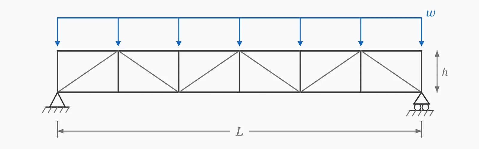
A parallel-chord truss behaves like a deep beam whose flanges have been replaced by chords. Reactions are wL/2, the midspan moment is wL²/8, and the peak chord force is that moment divided by the truss depth. Enter span, depth, uniform load and panel count to size the chords and understand how depth trades against chord force.
Calculator
Units:
m
Centre-to-centre distance between supports
m
Centre-to-centre between chords — aim for L/10 to L/15
kN/m
Total distributed load including self-weight
—
Bays along the span; sets the compression chord's unbraced length
Calculation Result
Press Calculate for the support reaction, the maximum midspan moment, the peak chord force and the panel length. Chord force is the number that sizes the top and bottom members; panel length sets the unbraced length of the compression chord.
Step-by-Step Solution
Preliminary design aid. Results follow the published formulas cited
below and are intended for estimating, study and early design. Final design must be
verified by a licensed Professional Engineer against the code in force for your project.
Key Benefits
✓Returns reaction, moment, chord force and panel length from four inputs
✓Makes the inverse relationship between depth and chord force explicit
✓Panel length feeds directly into the buckling check for the compression chord
✓Sensitivity chart shows how chord force falls as truss depth increases
✓Fast enough to compare truss geometries during scheme design
✓Shareable links and CSV export for design records
What Is Truss Analysis?
A truss carries load through a triangulated arrangement of members that act primarily in tension and compression rather than bending. For a parallel-chord truss the global behaviour mirrors that of a beam: the applied load produces a bending moment that varies along the span, and that moment is resisted by a force couple — compression in the top chord, tension in the bottom — separated by the truss depth. Because the lever arm is the full depth rather than a fraction of it, a truss uses far less material than a solid beam of the same span.
The equivalent beam method
Treating the truss as a beam gives the chord forces directly. The maximum moment for a simply supported span under uniform load is wL²/8 at midspan, and dividing by the depth h gives the peak chord force F = wL²/(8h). The method is accurate for chord forces in a parallel-chord truss because the chords genuinely form a constant-lever-arm couple. It is approximate for web members, whose forces follow the shear diagram and are largest near the supports.
Why span-to-depth ratio dominates the design
Since chord force scales as 1/h, a shallow truss pays for its slimness in chord material. Typical span-to-depth ratios run from about 10 to 15 for roof trusses and 8 to 12 for floor trusses, where deflection matters more. Going below a ratio of about 20 rarely makes sense: chord forces grow so large that the connections and the compression chord's buckling check become the binding constraints long before member strength does.
Formula
F_chord = wL² / (8h)
Maximum chord force in a simply supported parallel-chord truss under uniform load
Related Formulas
R = wL / 2
M_max = wL² / 8
L_panel = L / n
F_web ≈ V / sin θ
Variable Definitions
Symbol
Variable
Unit
Description
F_chord
Maximum Chord Force
kN
Peak axial force in the top and bottom chords at midspan — compression above, tension below.
w
Uniform Load
kN/m
Distributed load along the truss, including self-weight and the tributary width of roof or floor.
L
Span
m
Distance between support centrelines. Chord force grows with the square of this value.
h
Truss Depth
m
Centre-to-centre distance between chords — the lever arm of the resisting couple.
R
Support Reaction
kN
Vertical force at each support, half the total load for a symmetric case.
n
Number of Panels
—
Bays along the span. Sets the panel length and hence the compression chord's unbraced length.
How to Use This Calculator
Enter the span between support centrelinesUse the centre-to-centre bearing distance. Chord force grows with the square of span, so this is the most sensitive input after depth.
Enter the depth between chord centrelinesMeasure centre-to-centre between the top and bottom chords, not the overall depth including chord sections. A useful starting point is span divided by 12.
Include self-weight in the uniform loadThe load should cover roofing or decking, services, imposed load over the tributary width, and the truss's own weight — typically 0.15 to 0.30 kN/m for a steel roof truss of moderate span.
Choose the panel countMore panels give shorter web members and a shorter unbraced length for the compression chord, but more joints to fabricate. Panel lengths of 1.5 to 3 m are common in steel roof trusses.
Carry the results into the member checksSize the bottom chord for tension against the chord force, and check the top chord for buckling using the panel length as its unbraced length. The reaction sizes the end connection and the bearing detail.
Worked Examples
Example 1
A simply supported parallel-chord steel roof truss spans 12 m with a depth of 2.0 m and six panels. It carries a uniform load of 5 kN/m including self-weight. Find the reactions and chord forces.
Step-by-Step Solution
Total load: W = w × L = 5 × 12 = 60 kN
Support reaction: R = W/2 = 60/2 = 30.00 kN at each end
Maximum chord force: F = M/h = 90.00 / 2.0 = 45.00 kN
Panel length: L_panel = L/n = 12 / 6 = 2.00 m
Span-to-depth ratio: 12 / 2.0 = 6.0 — a deep truss, so chord forces are modest
Design consequence: the bottom chord carries 45 kN tension, the top chord 45 kN compression over an unbraced length of 2.0 m. That combination is comfortably handled by a small angle or hollow section.
Example 2
The same truss and the same load, but the depth is reduced from 2.0 m to 0.8 m to fit a shallower roof zone. This is where the inverse relationship becomes expensive.
Step-by-Step Solution
Reaction and moment are unchanged: R = 30.00 kN, M = 90.00 kN·m — depth does not affect global equilibrium
Maximum chord force: F = M/h = 90.00 / 0.8 = 112.50 kN
Panel length is unchanged at 2.00 m for six panels
Span-to-depth ratio: 12 / 0.8 = 15.0
Comparison: depth fell by a factor of 2.5 and chord force rose by exactly 2.5, from 45.00 to 112.50 kN
The compression chord now carries 112.5 kN over a 2.0 m unbraced length, which pushes it from a small angle into a substantial hollow section — and the end connections grow with it.
The lesson: reclaiming 1.2 m of ceiling height costs 150% more chord force. That trade is worth making consciously rather than by default.
Depth Sensitivity
Chord force is inversely proportional to depth, so the curve falls steeply at shallow depths and then flattens. The knee of that curve is where extra depth stops paying for itself — usually around a span-to-depth ratio of 10 to 12. The marker shows your current depth.
Max Chord Force vs Truss Depth (h)
Recomputed live from your inputs. The marker shows your current value.
Line chart of Max Chord Force against Truss Depth (h). The same
values are listed in the data table below.
Values plotted above, sampled across the truss depth (h) range.
How to Interpret Your Results
Chord force is the number that sizes the truss, and its usefulness comes from comparing it against the span-to-depth ratio that produced it. The bands below relate the computed force to the member types it typically implies in steel roof and floor trusses.
Max Chord Force: < 50Light chord forces
A maximum chord force of your result kN is modest, and suggests a generous truss depth relative to span. Small angles or light hollow sections will handle this. Check the compression chord for buckling over the panel length before finalising.
Max Chord Force: 50 – 300Typical structural truss range
A maximum chord force of your result kN is normal for roof and floor trusses in buildings. Size the bottom chord for tension and check the top chord for buckling using the panel length as its unbraced length — compression usually governs the chord selection.
Max Chord Force: 300 – 1000Heavy chords — check the connections
A maximum chord force of your result kN is substantial. At this level the joints often govern the design rather than the members, and increasing truss depth is usually cheaper than upsizing chords and their connections together.
Max Chord Force: ≥ 1000Very high chord forces — revisit the geometry
A maximum chord force of your result kN indicates either a very long span or a truss too shallow for it. Before sizing members, check whether extra depth is available: chord force is inversely proportional to depth, so a modest increase pays back immediately.
Panel Length: ≥ 4Long panels — compression chord buckling will govern
A panel length of your result m gives the compression chord a long unbraced length, and buckling capacity falls with the square of it. Adding panels, or bracing the top chord at intermediate points, is usually cheaper than upsizing the chord.
Common Mistakes to Avoid
Using the overall depth instead of the chord centreline distance
Why it matters:The lever arm of the resisting couple runs between chord centroids, not between the outer faces. Using overall depth overstates the lever arm and understates chord force, and the error grows as chords get deeper.
✓How to avoid it:Measure centre-to-centre between the top and bottom chord centroids. For deep chord sections this can be 10% less than the overall depth.
Forgetting to include the truss self-weight
Why it matters:A steel roof truss weighs roughly 0.15 to 0.30 kN/m over moderate spans, which on a lightly loaded roof can be 5 to 10% of the total. Omitting it understates every result by that margin.
✓How to avoid it:Estimate self-weight from an initial member sizing, include it in w, and revisit once the members are chosen.
Sizing the compression chord without a buckling check
Why it matters:The top chord is a compression member with an unbraced length set by the panel spacing. Sizing it on axial strength alone ignores buckling, which almost always governs.
✓How to avoid it:Use the panel length as the unbraced length and run a proper buckling check. Consider whether the roof deck genuinely braces the chord, since that assumption is often claimed but rarely detailed.
Applying the equivalent beam method to web members
Why it matters:The method gives chord forces accurately because the chords form a constant-lever-arm couple. Web member forces follow the shear diagram instead, peaking near the supports where this calculation says nothing.
✓How to avoid it:Compute web forces from panel shear as V/sin θ, or run a joint-by-joint analysis. Web members near the supports carry the highest forces, not those at midspan.
Treating the result as valid for a pitched truss
Why it matters:The equivalent beam method assumes parallel chords and therefore a constant lever arm. In a pitched truss the depth varies along the span, so chord force does not simply track the moment diagram.
✓How to avoid it:For pitched, bowstring or tapered trusses, use the local depth at each panel or run a full analysis. Applying a single depth to a varying-depth truss can be significantly unconservative near the eaves.
Ignoring deflection
Why it matters:A truss satisfying member strength can still deflect excessively, particularly a shallow one. Truss deflection includes chord axial shortening and lengthening plus web deformation, and shallow trusses are disproportionately flexible.
✓How to avoid it:Check deflection against the serviceability limit for the application, and remember that the span-to-depth ratios recommended for trusses exist largely to keep deflection acceptable.
Practical Applications
▸Preliminary sizing of parallel-chord roof and floor trusses
▸Estimating chord forces for steel joist and open-web joist selection
▸Checking existing trusses against increased roof or plant loading
▸Comparing truss depths during scheme design and roof zone coordination
▸Sizing end connections and bearing details from the reaction
▸Setting panel spacing to control compression chord buckling
Industry Use Cases
Industrial and warehouse construction
Long-span portal and truss roofs are optimised against roof zone depth. Because chord force varies inversely with depth, designers run this calculation across candidate depths to find where extra steel in the chords starts to outweigh the cost of a taller building envelope.
Steel joist manufacturing
Open-web steel joist load tables are generated by inverting this calculation across combinations of span, depth and load. Specifiers use the same relationship in reverse to check whether a catalogue joist suits a non-standard loading.
Timber truss fabrication
Nail-plated timber trusses are governed as much by plate capacity at the joints as by member strength. Chord force sets the required plate size, so reducing it through added depth often removes a plate size from the whole run.
Expert Tips
💡Chord force is inversely proportional to depth — doubling depth halves the force in both chords at once.
💡Aim for a span-to-depth ratio of 10 to 15 for roof trusses and 8 to 12 for floor trusses where deflection matters more.
💡The top chord's unbraced length is the panel length, not the span. More panels means a lighter compression chord.
💡Web forces peak at the supports while chord forces peak at midspan — size each where it is worst, not at a single section.
💡Where roof deck is claimed as bracing to the top chord, make sure the connection actually delivers that restraint.
💡Adding depth is nearly always cheaper than upsizing chords, because the connections grow with the chords.
Advantages & Limitations
Advantages
✓Gives chord forces directly from four readily available inputs
✓Accurate for the chords of a parallel-chord truss, which is where most of the material sits
✓Makes the depth-versus-chord-force trade explicit and quantifiable
✓Returns panel length, feeding straight into the compression chord buckling check
✓Fast enough to sweep across candidate geometries during scheme design
Limitations
!Valid for parallel-chord trusses only — pitched and tapered trusses have a varying lever arm
!Assumes a simply supported span with a uniformly distributed load
!Gives chord forces only; web member forces follow the shear diagram and need separate calculation
!Assumes pinned joints with no secondary bending, whereas welded joints carry some moment
!Takes no account of deflection, which frequently governs shallow trusses
!Does not check member capacity, buckling or connections — these are separate steps
!Assumes loads are applied at panel points; loads between nodes induce local bending in the chord
Chord Force by Span-to-Depth Ratio
The same 12 m truss carrying 5 kN/m, at different depths. The moment never changes — only the lever arm resisting it does, which is what makes depth such a powerful and cheap variable.
Chord forces for a 12 m simply supported parallel-chord truss under 5 kN/m. Moment is 90 kN·m in every case.
For a parallel-chord truss, find the maximum moment as wL²/8 and divide by the truss depth: F = wL²/(8h). The top chord takes that force in compression and the bottom chord in tension. A 12 m truss 2 m deep under 5 kN/m gives 45 kN.
What is a good span-to-depth ratio for a truss?
Roof trusses typically run 10 to 15, floor trusses 8 to 12 because deflection matters more. Below about 20 the chord forces and connections become the binding constraint, and the truss stops being an efficient way to span.
Why does truss depth reduce chord force?
The chords resist the applied moment as a force couple, and the depth is the lever arm of that couple. Since moment equals force times lever arm, doubling the depth halves the force needed to resist the same moment.
Where is the chord force greatest?
At midspan for a uniformly loaded simply supported truss, because that is where the moment peaks. Web member forces behave oppositely, peaking near the supports where shear is largest — so each member type is sized at a different location.
Is the equivalent beam method accurate?
For chord forces in a parallel-chord truss, yes — the chords genuinely form a constant-lever-arm couple. It is approximate for web members and unreliable for pitched or tapered trusses, where the lever arm varies along the span.
How do I find web member forces?
Web forces follow the shear diagram. For a diagonal at angle θ carrying panel shear V, the force is approximately V/sin θ. Shear is highest at the supports, so the end diagonals are the most heavily loaded web members.
What is the unbraced length of the top chord?
The panel length, unless the roof deck or purlins provide genuine intermediate restraint. Since buckling capacity falls with the square of unbraced length, adding panels is often cheaper than upsizing the compression chord.
Does this work for a pitched roof truss?
Not directly. A pitched truss has a depth that varies along the span, so a single depth value does not represent the lever arm. Use the local depth at each panel point, or run a full analysis — applying the midspan depth throughout is unconservative near the eaves.
How much does a steel truss weigh?
For moderate spans, roughly 0.15 to 0.30 kN/m of truss length, rising with span and load. Estimate it, include it in the applied load, then revisit once members are sized — on lightly loaded roofs it can be 5 to 10% of the total.
Should I check truss deflection?
Yes, and for shallow trusses it frequently governs. Truss deflection comes from axial deformation of the chords and webs rather than flexure, so it is not captured by a beam deflection formula. The recommended span-to-depth ratios exist largely to keep it acceptable.
Glossary
Chord
The top or bottom member running the length of a truss, carrying the axial force couple that resists the applied moment.
Web member
A diagonal or vertical member connecting the chords, carrying the shear between panel points.
Panel
One bay of a truss between adjacent web member intersections; its length sets the compression chord's unbraced length.
Panel point
A node where web members meet a chord, and where loads should be applied to avoid local chord bending.
Parallel-chord truss
A truss whose top and bottom chords are parallel, giving a constant lever arm along the span.
Span-to-depth ratio
Span divided by truss depth; the primary measure of truss efficiency, typically 10 to 15 for roofs.
Equivalent beam method
A technique that finds chord forces by treating the truss as a beam and dividing its moment by the truss depth.
Lever arm
The distance between the chord centroids, over which the resisting force couple acts.
Secondary bending
Bending induced in truss members by joint rigidity, which the idealised pin-jointed analysis does not capture.
Scientific & Standards References
AISC 360-22 §E and §D — Design of Members for Compression and Tension — American Institute of Steel Construction
Steel Joist Institute — Standard Specifications and Load Tables for Open Web Steel Joists — Steel Joist Institute
Hibbeler, R. C., Structural Analysis, 10th Edition — Chapter 3: Analysis of Statically Determinate Trusses — Pearson
EN 1993-1-1 §5.1.5 and Annex BB — Truss analysis and buckling lengths of chords — CEN
AISC Design Guide 31: Castellated and Cellular Beam Design — American Institute of Steel Construction
Conclusion
A parallel-chord truss resists its applied moment as a force couple between the chords, so chord force is simply wL²/(8h) — inversely proportional to depth. That single relationship drives the whole design: doubling the depth halves the chord force, and since connections grow with chord size, added depth is almost always cheaper than added chord. Size the bottom chord for tension, check the top chord for buckling over the panel length rather than the span, and remember that web forces peak at the supports while chord forces peak at midspan.
Try your own geometry above, then sweep the depth in the chart to find where extra depth stops paying for itself.