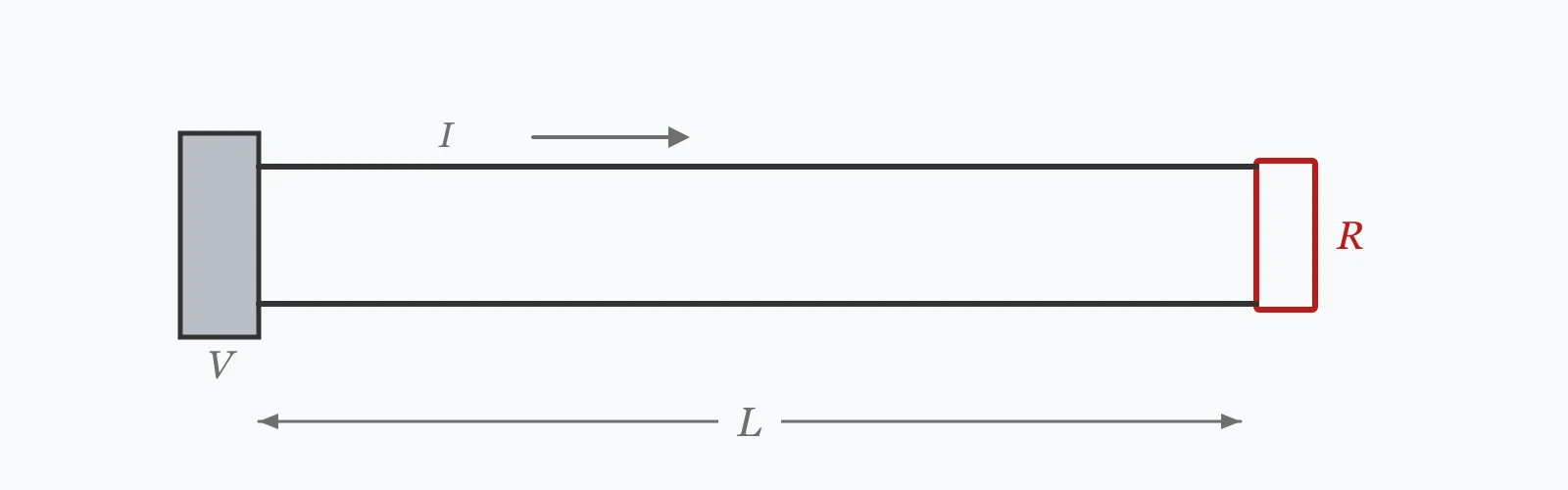
American Wire Gauge is a geometric scale, not an arbitrary list: every three gauge numbers doubles the cross-sectional area. Enter a gauge number, conductor material, run length and current to get the diameter, area, resistance per kilometre, and the round-trip voltage drop — plus the nearest IEC metric size for substitution.
Calculator
Units:
Larger number, thinner wire. Enter −1 for 00, −2 for 000, −3 for 0000
Aluminium has 64% of copper's conductivity
m
Distance to the load. The drop counts the return conductor too
A
Current the conductor carries
Calculation Result
Press Calculate for the conductor diameter, cross-sectional area, DC resistance per kilometre at 20 °C, and the voltage drop over the run you entered, counting both the outgoing and returning conductor.
Step-by-Step Solution
Preliminary design aid. Results follow the published formulas cited
below and are intended for estimating, study and early design. Final design must be
verified by a licensed Professional Engineer against the code in force for your project.
Key Benefits
✓Uses the defining AWG formula rather than an interpolated lookup table
✓Covers the whole range including 0, 00, 000 and 0000
✓Handles copper and aluminium, which differ by 64% in conductivity
✓Gives the round-trip voltage drop, not the one-way figure
✓Suggests the nearest IEC 60228 metric size at or above the area
✓Shareable links and CSV export for installation records
What Is AWG Wire Size Converter?
American Wire Gauge assigns a number to each conductor size, running from 0000 (the thickest in common use) down through 0, then 1, 2, 3 and upward as the wire gets thinner. It is defined by two fixed points — 0.005 inches at gauge 36 and 0.46 inches at gauge 0000 — with 39 geometric steps between them. Every gauge is therefore the previous one multiplied by a constant ratio, which is where the useful shortcuts come from.
The two rules worth memorising
Because the scale is geometric, three gauge numbers change the area by a factor of very nearly exactly two, and ten gauge numbers by a factor of ten. So AWG 10 has twice the area of AWG 13 and ten times the area of AWG 20. Since resistance is inversely proportional to area, the same rules run the other way for resistance: three gauges thinner doubles the resistance per metre.
Why aluminium needs more than two gauge sizes
Aluminium's resistivity is 2.826×10⁻⁸ Ω·m against copper's 1.724×10⁻⁸, a ratio of 1.639. To match a copper conductor's resistance, an aluminium one needs 1.639 times the area. Two AWG sizes larger gives only 1.59 times, so it falls slightly short; three sizes gives 2.0 times and overshoots. The common rule of thumb — go up two sizes for aluminium — is close but marginally optimistic, which matters on a long run already near its voltage drop limit.
Formula
d = 0.127 · 92^((36 − n)/39) mm
Conductor diameter for AWG number n. Use 0 for gauge 0, and −1, −2, −3 for 00, 000, 0000
Related Formulas
A = π · d² / 4
R = ρ / A
V_drop = 2 · I · R · L
A₂/A₁ = 92^(2(n₁−n₂)/39)
Variable Definitions
Symbol
Variable
Unit
Description
n
AWG Number
—
Gauge number. Larger means thinner. 0 for gauge 0, −1 to −3 for 00 to 0000.
d
Conductor Diameter
mm
Diameter of the bare conductor, excluding insulation.
A
Cross-Sectional Area
mm²
The quantity that governs both resistance and current-carrying capacity.
ρ
Resistivity
Ω·m
1.724×10⁻⁸ for annealed copper, 2.826×10⁻⁸ for aluminium, both at 20 °C.
R
Resistance
Ω/km
DC resistance at 20 °C. Rises about 0.39% per °C for copper.
L
Run Length
m
One-way distance. The voltage drop counts the return conductor as well.
How to Use This Calculator
Enter the gauge number, remembering it runs backwardsLarger numbers are thinner wires. For the gauges written 0, 00, 000 and 0000 — spoken as one-aught through four-aught — enter 0, −1, −2 and −3, which keeps the geometric formula valid across the whole scale.
Choose the conductor materialAluminium carries 64% of copper's conductivity for the same area, so its resistance and voltage drop are 1.64 times higher at the same gauge. It also creeps under terminal pressure and needs terminations rated for it.
Enter the one-way run lengthMeasure to the load, not there and back. The calculator doubles it internally, because current flows out along one conductor and returns along another and both contribute to the drop.
Read the voltage drop against your supply, not in isolationThree volts is negligible on a 230 V circuit and disastrous on a 12 V one. The usual limit is 3% for a final circuit and 5% overall, so convert the drop to a percentage of the actual system voltage.
Treat the resistance as a 20 °C figureCopper gains about 0.39% resistance per degree, so a conductor running at 70 °C carries roughly 20% more resistance than shown. For a cable already near its voltage drop limit, that margin matters.
Worked Examples
Example 1
AWG 12 copper, a 30 m run carrying 10 A. Find the conductor size, resistance and voltage drop.
Step-by-Step Solution
Diameter: d = 0.127 × 92^((36 − 12)/39) = 0.127 × 92^0.6154 = 2.053 mm
Voltage drop, counting both conductors: 2 × 10 × 0.1563 = 3.126 V
Nearest IEC 60228 size at or above 3.309 mm²: 4 mm²
Interpretation: 3.126 V is 1.36% of a 230 V supply, comfortably within the 3% usually allowed for a final circuit. On a 12 V DC circuit the same drop would be 26% — the wire is unchanged, but the verdict is completely different.
Example 2
The same AWG 12 conductor in aluminium rather than copper, on the same 30 m run at 10 A.
Step-by-Step Solution
Diameter and area are unchanged: 2.053 mm and 3.309 mm² — the gauge describes geometry, not material
Aluminium resistivity is 2.826×10⁻⁸ Ω·m against copper's 1.724×10⁻⁸
Resistance: 2.826×10⁻⁸ / 3.309×10⁻⁶ = 8.541 Ω/km, up from 5.210
Voltage drop: 2 × 10 × 8.541 × 0.030 = 5.125 V, against 3.126 V for copper
The ratio is 1.639, exactly the ratio of the two resistivities.
To recover the copper performance, the aluminium conductor needs 1.639 times the area. Two AWG sizes larger — AWG 10 — gives 5.261 mm², which is 1.59 times: slightly short.
Three sizes larger, AWG 9, would give almost exactly twice the area and overshoot. The familiar rule of going up two sizes for aluminium is close but marginally optimistic, and on a run already near its drop limit that shortfall is real.
Gauge Sensitivity
Area falls geometrically as the gauge number rises, and resistance climbs the same way inverted. Switch between the series to see how sharply thin gauges lose capacity — the curve is exponential, not linear, which is why a couple of sizes makes such a difference. The marker shows your current gauge.
Cross-Sectional Area vs AWG Number
Recomputed live from your inputs. The marker shows your current value.
Line chart of Cross-Sectional Area against AWG Number. The same
values are listed in the data table below.
Values plotted above, sampled across the awg number range.
How to Interpret Your Results
The area is the number that governs everything else — resistance, voltage drop and current capacity all follow from it. The voltage drop is only meaningful once compared against the system voltage.
Cross-Sectional Area: < 1Fine conductor — signal or internal wiring
A cross-section of your result mm² is in the range used for signal, control and equipment-internal wiring. It is fragile to terminate and has high resistance per metre, so it is rarely appropriate for power distribution over any distance.
Cross-Sectional Area: 1 – 10General wiring range
A cross-section of your result mm² covers the majority of final circuits — lighting, socket outlets and small appliances. Check the voltage drop over the actual run length as well as the current rating, since long runs are usually limited by drop rather than by heating.
Cross-Sectional Area: 10 – 100Sub-main and feeder range
A cross-section of your result mm² suits sub-mains, feeders and large fixed loads. At this size the difference between copper and aluminium becomes commercially significant, and aluminium is common in this range and above.
Cross-Sectional Area: ≥ 100Distribution conductor
A cross-section of your result mm² is distribution-scale. Conductors this size are usually specified in mm² directly rather than by AWG, and at this scale skin effect begins to raise the effective AC resistance above the DC value shown.
Voltage Drop (round trip): ≥ 6.9Large drop — check against your supply voltage
A drop of your result V exceeds 3% of a 230 V supply, the usual limit for a final circuit. Use a larger conductor, shorten the run, or verify against the actual system voltage — on a 400 V system the same drop is well within limits.
Common Mistakes to Avoid
Assuming a larger AWG number means a larger wire
Why it matters:The scale runs backwards. AWG 20 is much thinner than AWG 10 — a tenth of the area, in fact. The inversion catches out anyone used to metric sizes, where the number is the area itself.
✓How to avoid it:Read AWG as a count of drawing steps rather than a size. Remembering that ten gauge numbers change the area tenfold makes the direction unambiguous.
Halving the run length or forgetting to double it
Why it matters:Current flows to the load along one conductor and back along another, so the resistance in the loop is twice the one-way figure. Using the one-way resistance halves the calculated drop.
✓How to avoid it:Enter the one-way distance and let the calculation double it, as this one does. For three-phase circuits the factor is √3 rather than 2, because the return path is shared.
Judging the voltage drop without the system voltage
Why it matters:A drop of 3 V is 1.3% on a 230 V circuit and 25% on a 12 V one. The absolute figure carries no information about acceptability on its own.
✓How to avoid it:Convert to a percentage of the supply voltage. Low-voltage DC systems — vehicles, solar, LED lighting — are almost always limited by voltage drop rather than by conductor heating.
Going up two AWG sizes for aluminium without checking
Why it matters:Aluminium needs 1.639 times the area to match copper's resistance, and two AWG sizes give only 1.59 times. The rule of thumb is 3% short, which is invisible on a short run and real on a long one.
✓How to avoid it:Compare the actual resistance figures rather than applying the gauge shortcut. Where the drop is already close to the limit, take the third size up.
Using the 20 °C resistance for a loaded conductor
Why it matters:Copper's resistance rises about 0.39% per degree. A conductor operating at its 70 °C insulation limit has roughly 20% more resistance than the tabulated figure, and correspondingly more voltage drop.
✓How to avoid it:Apply a temperature correction for conductors expected to run hot, particularly where several cables are bunched together and cannot dissipate heat freely.
Treating the area as the current rating
Why it matters:Cross-section determines resistance exactly, but current-carrying capacity also depends on insulation type, installation method, ambient temperature, grouping and whether the cable is in free air, in conduit or buried.
✓How to avoid it:Use the area for resistance and voltage drop, and a proper ampacity table with the applicable derating factors for the current rating. The two calculations answer different questions.
Practical Applications
▸Converting American wire gauges to metric conductor sizes
▸Estimating voltage drop over a cable run
▸Comparing copper and aluminium conductors of the same gauge
▸Selecting an IEC equivalent for an AWG-specified cable
▸Checking resistance for a low-voltage DC installation
Equipment imported from North America arrives with AWG-specified conductors that have to be matched to metric cable at the connection point. The nearest metric size at or above the AWG area is the safe substitution, since it can never be a downgrade in resistance.
Low-voltage DC systems
Solar, vehicle and LED installations run at 12, 24 or 48 V, where voltage drop rather than heating almost always sets the conductor size. A drop that would be trivial on mains is a large fraction of a 12 V supply, so runs are kept short and conductors generously sized.
Electronics and control panels
Internal wiring and signal cabling sit in the AWG 18 to 30 range, where the concern is termination reliability and mechanical strength rather than voltage drop. Below about AWG 30 the conductor becomes fragile enough that it is rarely used outside equipment.
Expert Tips
💡Three gauge numbers double the area; ten gauge numbers multiply it by ten.
💡Larger AWG number means thinner wire — the scale counts drawing steps.
💡Aluminium needs 1.64 times the area, a little more than two AWG sizes.
💡Voltage drop counts both conductors, so it uses twice the one-way length.
💡A 3 V drop is 1.3% on 230 V and 26% on 12 V — always convert to a percentage.
💡Copper's resistance rises about 20% between 20 °C and a 70 °C operating limit.
Advantages & Limitations
Advantages
✓Uses the defining geometric formula, so every gauge is exact rather than interpolated
✓Covers the aught sizes that lookup tables often handle inconsistently
✓Reports the round-trip voltage drop, which is the figure that matters
✓Handles both copper and aluminium with their actual resistivities
✓Gives the nearest IEC metric size, which is never a downgrade
Limitations
!Gives DC resistance at 20 °C; operating temperature raises it appreciably
!Takes no account of skin effect, which matters for large conductors at mains frequency
!Does not give ampacity, which depends on insulation, grouping and installation method
!Assumes a solid conductor of nominal dimensions; stranded cable differs slightly
!The voltage drop uses a factor of 2 for single-phase; three-phase circuits use √3
!Does not account for conductor tolerance or plating
!The metric equivalent is a nearest size, not a code-compliant substitution
The AWG Scale in Copper
Diameter, area and resistance across the common range, with the voltage drop for a 30 m run at 10 A. Follow the area column down three rows at a time and it halves each step — that is the geometric progression the scale is built on.
Annealed copper at 20 °C. Compare gauge 2 with gauge 12: ten steps, and the area falls from 33.63 to 3.309 mm² — a factor of 10.16, which is the ten-gauge rule. Compare 12 with 6: six steps, 3.309 to 13.30 mm², a factor of 4.02, or two doublings.
Find the diameter with d = 0.127 × 92^((36 − n)/39) in millimetres, then the area with πd²/4. AWG 12 gives 2.053 mm and 3.309 mm².
Why does a higher AWG number mean a thinner wire?
Because the number counts drawing operations. Wire was originally drawn through successively smaller dies, and each pass made it thinner — so a higher number means more passes and a smaller conductor.
How many AWG sizes double the wire area?
Three. The scale is geometric, so three gauge steps change the area by a factor of very nearly exactly two, and ten steps change it by a factor of ten.
What is AWG 12 in mm²?
3.309 mm², with a diameter of 2.053 mm and a DC resistance of 5.21 Ω/km in copper at 20 °C. The nearest IEC size at or above it is 4 mm².
What do 0, 00, 000 and 0000 mean?
They are the gauges above 1, spoken as one-aught to four-aught, or written 1/0 to 4/0. Enter them as 0, −1, −2 and −3, which keeps the geometric formula valid across the whole range.
How much bigger does aluminium wire need to be?
1.639 times the area, matching the ratio of the two resistivities. Two AWG sizes larger gives 1.59 times, slightly short; three sizes gives 2.0 times and overshoots.
How do I calculate voltage drop from AWG?
Multiply the resistance per metre by the run length, double it for the return conductor, and multiply by the current. AWG 12 over 30 m at 10 A gives 3.126 V.
Does AWG tell me the current rating?
No. Area sets the resistance exactly, but current capacity also depends on insulation type, installation method, ambient temperature and how many cables are grouped together. Use an ampacity table with the applicable derating factors.
Does wire resistance change with temperature?
Yes, by about 0.39% per °C for copper. A conductor at a 70 °C insulation limit has roughly 20% more resistance than the 20 °C figure, with correspondingly more voltage drop.
What is the metric equivalent of AWG 14?
2.081 mm², so 2.5 mm² is the nearest IEC 60228 size at or above it. Substituting upward is safe; substituting to 1.5 mm² would be a reduction in area and therefore in capacity.
Glossary
AWG
American Wire Gauge, a geometric scale where a larger number means a thinner conductor.
Aught
The gauges above 1, written 0 to 0000 and spoken one-aught to four-aught.
Cross-sectional area
The conductor's area, which determines resistance and underpins current capacity.
Resistivity
A material's intrinsic resistance per unit length and area, in Ω·m.
Voltage drop
Voltage lost along a conductor, equal to current times loop resistance.
IEC 60228
The international standard defining preferred metric conductor sizes.
Ampacity
The current a conductor may carry continuously without exceeding its temperature limit.
Skin effect
The tendency of alternating current to concentrate near a conductor's surface, raising effective resistance.
Annealed copper
Softened copper used for electrical conductors, the reference material for resistivity.
Derating
Reduction of a conductor's rated current for grouping, ambient temperature or installation method.
Scientific & Standards References
ASTM B258 — Standard Specification for Nominal Diameters and Cross-Sectional Areas of AWG Sizes of Solid Round Wires — ASTM International
IEC 60228 — Conductors of insulated cables — International Electrotechnical Commission
NFPA 70 (National Electrical Code), Chapter 9 Table 8 — Conductor Properties — National Fire Protection Association
BS 7671 — Requirements for Electrical Installations (IET Wiring Regulations), Appendix 4 — Institution of Engineering and Technology
CRC Handbook of Chemistry and Physics — Electrical Resistivity of Pure Metals — CRC Press
Conclusion
AWG is a geometric scale with two rules that reconstruct most of the table: three gauge numbers double the area, and ten multiply it by ten. Once that is internalised, the inverted numbering stops being a nuisance. What the gauge does not tell you is just as important. It fixes the geometry but not the material, and aluminium at the same gauge has 1.64 times the resistance — a little more than two sizes' worth, so the familiar rule of going up two is marginally optimistic. It fixes resistance but not current capacity, which depends on insulation, grouping, ambient temperature and installation method. And a voltage drop figure means nothing until it is set against the supply: the 3.126 V calculated for AWG 12 over 30 m is 1.36% of a 230 V circuit and 26% of a 12 V one.
Enter a gauge, material and run length above to get the area, resistance and drop.