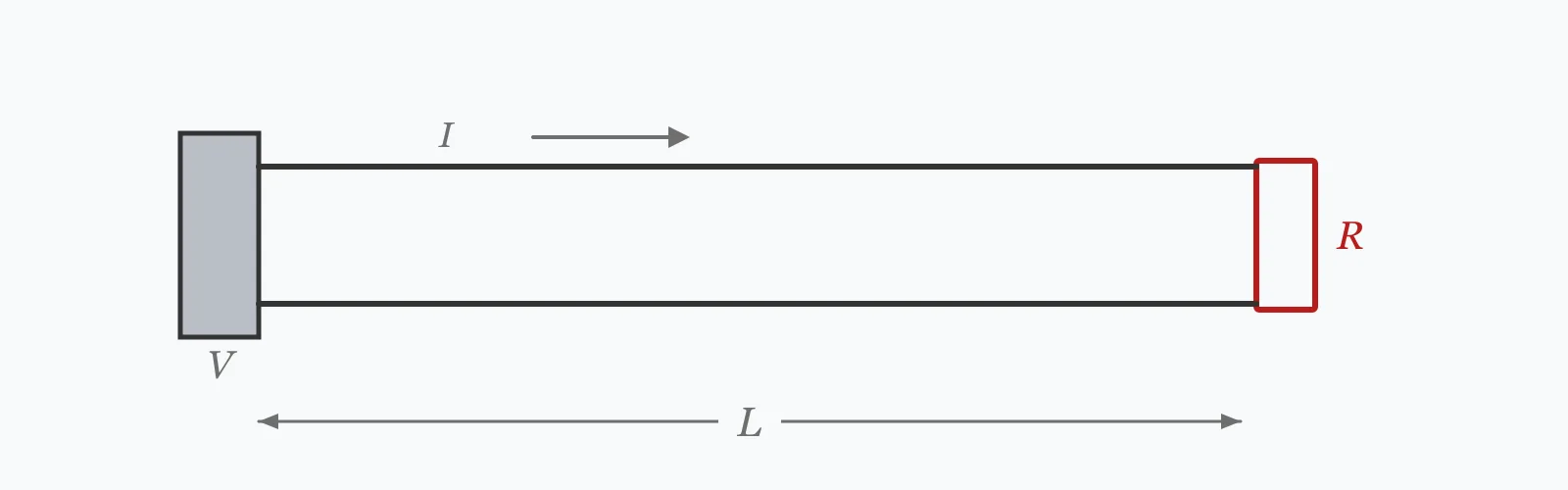
Two independent criteria size a conductor: it must carry the current without overheating, and it must deliver the voltage at the far end. This calculator estimates the first from a current density in A/mm² and the second from a 3% volt drop limit, then picks the next standard size above whichever governs. It is a preliminary aid — final selection needs the code ampacity tables and their derating factors.
Calculator
Units:
A
Design current of the circuit
A/mm²
4–6 for copper in ordinary conditions; lower where grouped or insulated
V
Nominal supply voltage; the 3% limit is taken from this
m
Route distance from supply to load
Calculation Result
Press Calculate for the area required on current, the area required to hold voltage drop to 3%, and the next standard size above the larger of the two. Compare the two areas — whichever is bigger is what governs your design.
Step-by-Step Solution
Preliminary design aid. Results follow the published formulas cited
below and are intended for estimating, study and early design. Final design must be
verified by a licensed Professional Engineer against the code in force for your project.
Key Benefits
✓Applies both sizing criteria and shows which one governs
✓Recommends the next standard metric size above the requirement
✓Makes the crossover between thermal and volt drop sizing visible
✓States plainly that it does not replace code ampacity tables
✓Sensitivity chart shows how the volt drop requirement grows with run length
✓Shareable links and CSV export for design records
What Is Wire Size?
A conductor must satisfy two separate requirements. Thermally, it must carry the design current continuously without exceeding its insulation temperature rating — a safety limit. Electrically, it must deliver enough voltage at the load — a performance limit. The two are independent, and the required cross-section is the larger of the two answers. This calculator estimates both and takes the larger.
Current density is an approximation, not an ampacity
Real cable ratings come from tabulated ampacities that account for insulation type, installation method, grouping, ambient temperature and thermal resistivity of the surroundings — a cable clipped to a wall carries considerably more than the same cable buried in insulation. This calculator uses a single current density in A/mm², typically 4 to 6 for copper in ordinary conditions. It gives a defensible first estimate, and nothing more.
Why length changes which criterion wins
The area needed for current does not depend on length at all. The area needed for volt drop is directly proportional to it. So on a short run the thermal requirement governs and the volt drop requirement is trivial, while beyond about 30 metres for a typical low-voltage circuit the volt drop requirement overtakes and then keeps growing. Doubling the run doubles the area needed on volt drop, while the thermal requirement does not move.
Formula
A_current = I / J
Cross-section from current and an assumed current density
Related Formulas
A_VD = 2 ρ I L / (0.03 V)
A_required = max(A_current, A_VD)
I_z ≥ I_b / (C_a · C_g · C_i)
Variable Definitions
Symbol
Variable
Unit
Description
I
Load Current
A
Design current of the circuit, not the protective device rating.
J
Current Density
A/mm²
Assumed permissible current per unit area. 4 to 6 for copper in ordinary conditions.
A_current
Area from Current
mm²
Cross-section the thermal criterion requires. Independent of run length.
A_VD
Area from Volt Drop
mm²
Cross-section needed to hold the drop to 3%. Directly proportional to length.
ρ
Resistivity
Ω·mm²/m
0.0175 for copper at 20 °C; aluminium is about 0.028.
L
One-Way Length
m
Route distance from supply to load.
How to Use This Calculator
Use the design current, not the breaker ratingSize on the current the circuit will actually carry. Using the protective device rating overstates the requirement, though the device rating must still fall between the design current and the cable's rated capacity.
Choose the current density for the conditions4 to 6 A/mm² suits copper in ordinary conditions. Reduce it where cables are grouped, run through insulation, or in high ambient temperature — all of which sharply reduce real ampacity.
Compare the two areas to see which governsIf the volt drop area exceeds the current area, length is driving the design. If not, the thermal criterion is. Knowing which tells you whether a shorter route or a larger cable is the effective remedy.
Confirm against the code ampacity tablesThis is the essential step. Take the tabulated rating for your cable type and installation method, apply the derating factors for ambient temperature, grouping and thermal insulation, and check the result exceeds the design current.
Adjust for three-phaseThe volt drop area here uses the single-phase factor of two. For a balanced three-phase circuit the requirement is about 13% smaller, so the calculation is conservative rather than wrong.
Worked Examples
Example 1
A 30 A load at 240 V runs 30 m from the distribution board. Using a current density of 4 A/mm², estimate the conductor size.
Step-by-Step Solution
Area from current: A = I/J = 30 / 4 = 7.5 mm²
Maximum permitted drop: 3% of 240 V = 7.2 V
Area from volt drop: A = 2ρIL / VD_max = 2 × 0.0175 × 30 × 30 / 7.2
= 31.5 / 7.2 = 4.4 mm²
The current criterion gives 7.5 mm² and volt drop gives 4.4 mm², so current governs
Next standard size above 7.5 mm²: 10 mm²
Assessment: at 30 m the thermal requirement is still the binding one. This will change as the run gets longer — the current figure stays at 7.5 mm² while the volt drop figure grows with length.
Example 2
The same 30 A load at 240 V, but run 200 m to an outbuilding. This is where the two criteria swap places decisively.
Step-by-Step Solution
Area from current: unchanged at 30 / 4 = 7.5 mm² — length does not affect the thermal requirement
Area from volt drop: 2 × 0.0175 × 30 × 200 / 7.2 = 210 / 7.2 = 29.2 mm²
Volt drop now requires nearly four times the area that current does
Next standard size above 29.2 mm²: 35 mm²
Comparison against the 30 m case: the recommended size has gone from 10 mm² to 35 mm² for exactly the same load.
The crossover happened at about 51 m, where the volt drop requirement first exceeded 7.5 mm².
For a run this long, distributing at a higher voltage and transforming down locally is often cheaper than the copper — the required area falls with the square of the distribution voltage.
Run Length Sensitivity
The area required on current is a flat line — length does not affect it. The area required on volt drop rises linearly and crosses it, and from that point onward volt drop governs the cable size. The recommended size steps up in standard increments. The marker shows your current length.
Required Area (3% VD) vs One-Way Length
Recomputed live from your inputs. The marker shows your current value.
Line chart of Required Area (3% VD) against One-Way Length. The same
values are listed in the data table below.
Values plotted above, sampled across the one-way length range.
How to Interpret Your Results
The two area outputs are the useful ones, because their comparison tells you which criterion is driving the design and therefore what would actually help. The recommended size is a starting point for the ampacity check, not its conclusion.
Recommended Size: < 6Small conductor
A size of your result mm² suits light circuits and short runs. Confirm against the ampacity table for your installation method — a cable in thermal insulation can carry less than half its free-air rating.
Recommended Size: 6 – 35Standard installation range
A size of your result mm² covers most final circuits and small sub-mains. Check which criterion produced it: if volt drop governs, a shorter route may be worth more than a larger cable.
Recommended Size: 35 – 120Large conductor — check the driver
A size of your result mm² is substantial. If volt drop is governing on a long run, consider distributing at higher voltage and transforming locally: the required area falls with the square of the distribution voltage.
Recommended Size: ≥ 120Very large conductor
A size of your result mm² is at the practical limit for a single cable — beyond this, installations normally use parallel conductors or busbar. Verify the design current and reconsider the distribution voltage before committing to this much copper.
Required Area (3% VD): ≥ 25Volt drop is driving the size
The volt drop requirement of your result mm² is large, which means run length rather than load is setting the cable size. Shortening the route, raising the distribution voltage or accepting a relocated distribution board are all more effective than upsizing.
Common Mistakes to Avoid
Treating this as an ampacity calculation
Why it matters:Current density is a rule of thumb. Real ampacity depends on insulation type, installation method, grouping, ambient temperature and thermal resistivity — a cable in insulation can carry less than half its clipped-direct rating. No single A/mm² figure captures that.
✓How to avoid it:Use this for a first estimate, then confirm against the tabulated rating for your cable type and installation method with all derating factors applied.
Checking only one criterion
Why it matters:Current and volt drop are independent requirements, and either can govern. A cable adequate on current can fail volt drop badly on a long run, and vice versa on a short heavily loaded one.
✓How to avoid it:Compute both and take the larger. The calculator returns both areas precisely so the comparison is visible.
Ignoring grouping and ambient derating
Why it matters:Several cables in a common trunking heat each other, and a cable in a warm plant room carries less than one in a cool corridor. Derating factors of 0.5 or lower are common in bunched installations.
✓How to avoid it:Apply the grouping, ambient and thermal insulation factors from the wiring rules. The derated rating must exceed the design current, not the tabulated free-air rating.
Forgetting the protective device coordination
Why it matters:The cable, the load and the protective device must be coordinated: the device rating must be at least the design current and no more than the cable's derated capacity. A correctly sized cable with an oversized breaker is not protected.
✓How to avoid it:Check the coordination condition explicitly. It is a separate requirement from either sizing criterion and is the one that actually makes the installation safe.
Using the 20 °C resistivity for volt drop
Why it matters:Copper resistivity rises about 0.4% per degree, so a conductor at 70 °C is roughly 20% more resistive than the 0.0175 Ω·mm²/m value used here. The volt drop area is understated by that margin.
✓How to avoid it:Treat the volt drop area as slightly optimistic, or repeat the calculation with the operating-temperature resistivity of about 0.021 Ω·mm²/m.
Overlooking the earth fault loop impedance
Why it matters:A long circuit may satisfy both current and volt drop and still fail to clear an earth fault within the required disconnection time, because the loop impedance is too high for the protective device to operate quickly.
✓How to avoid it:Check the earth fault loop impedance against the maximum permitted for the protective device. On long runs this is a third independent constraint, and it sometimes governs.
Practical Applications
▸First-pass conductor sizing during design
▸Checking whether current or volt drop governs a circuit
▸Estimating cable size for long runs to remote loads
▸Comparing distribution voltage options for a site
▸Sanity-checking a proposed cable schedule
▸Teaching the two independent sizing criteria
Industry Use Cases
Electrical design
Designers work from software that applies the full code tables and derating factors, but a hand estimate remains useful for scheme work and for sanity-checking output. Knowing which criterion governs is what tells you whether a design change will help.
Remote and rural supplies
Supplies to outbuildings and pumping stations routinely run hundreds of metres, where volt drop dominates completely. Because the required area falls with the square of distribution voltage, transforming locally is usually far cheaper than the copper it saves.
Industrial installations
Cables bunched in trunking and cable ladder derate heavily — factors of 0.5 or lower are common with many circuits together. The thermal criterion therefore governs far more often in industrial plant than the free-air figures would suggest.
Expert Tips
💡The current requirement is independent of length; the volt drop requirement is proportional to it.
💡Beyond roughly 30 m at low voltage, volt drop usually takes over as the governing criterion.
💡Required area falls with the square of distribution voltage — the argument for transforming locally.
💡Derating for grouping and ambient can halve a cable's real capacity; free-air ratings rarely apply.
💡Check earth fault loop impedance as a third constraint on long runs.
💡The protective device must sit between the design current and the cable's derated capacity.
Advantages & Limitations
Advantages
✓Applies both independent sizing criteria and shows which governs
✓Recommends a standard size rather than a bare area
✓Makes the length crossover explicit and visible
✓Fast enough to use during layout and route planning
✓Transparent about being an estimate rather than a code calculation
Limitations
!Uses a current density rule of thumb, not tabulated ampacity — the essential difference
!Takes no account of insulation type, installation method, grouping or ambient temperature
!The volt drop criterion is single-phase; three-phase needs about 13% less area
!Uses copper resistivity at 20 °C, understating volt drop at operating temperature
!Fixes the volt drop limit at 3%, whereas some circuits permit 5%
!Does not check earth fault loop impedance or protective device coordination
!The maximum current output is simply the selected area times the density, so it is circular rather than an independent rating
Which Criterion Governs, by Run Length
A 30 A load at 240 V with a current density of 4 A/mm². The current requirement never moves; the volt drop requirement grows with length and overtakes it at about 51 m.
30 A at 240 V single-phase, J = 4 A/mm², copper at 20 °C. Confirm every result against the code ampacity tables with derating applied.
Two independent criteria: the area needed to carry the current without overheating, and the area needed to hold voltage drop within its limit. Take the larger, then round up to the next standard size and confirm against the code ampacity tables.
What current density should I use for copper?
4 to 6 A/mm² is a reasonable rule of thumb for ordinary conditions. Reduce it where cables are grouped, run through thermal insulation, or in high ambient temperature. It is an approximation, not a substitute for tabulated ampacity.
Which governs, current or voltage drop?
It depends on the run length. The current requirement is independent of length while the volt drop requirement is proportional to it, so short runs are governed by current and long runs by volt drop. For a 30 A circuit at 240 V, the crossover is around 51 m.
Why does this not use NEC ampacity tables?
Because ampacity depends on insulation type, installation method, grouping and ambient temperature, which no single formula captures. This calculator gives a defensible first estimate from current density; the tables and their derating factors are the authoritative step that must follow.
What is cable derating?
The reduction applied to a cable's tabulated rating for the actual conditions — cables bunched together, in high ambient temperature, or surrounded by thermal insulation. Combined factors of 0.5 or lower are common, so the real capacity can be half the table figure.
How does distribution voltage affect cable size?
Strongly. For a given real power and a percentage volt drop limit, the required area falls with the square of the voltage. Doubling the distribution voltage quarters the copper, which is why long runs are transformed locally rather than distributed at low voltage.
Should I size on the breaker rating or the load current?
The design current, which is what the circuit actually carries. The breaker rating must then sit between the design current and the cable's derated capacity — that coordination is a separate requirement and is what makes the installation safe.
What is earth fault loop impedance and why does it matter?
The total impedance of the fault path back to the source. If it is too high, the protective device will not operate quickly enough to clear an earth fault within the required disconnection time. On long circuits it is a third independent constraint that sometimes governs.
Is aluminium cable a viable alternative?
Yes, and it is common in larger sizes. Aluminium's resistivity is about 1.6 times copper's, so it needs roughly 60% more cross-section for the same performance — but it is lighter and considerably cheaper, and terminations designed for it are readily available.
Can I use a smaller cable if the load is intermittent?
Sometimes, through diversity and duty factors, but with care. Cable heating has a long thermal time constant, so a load cycling on a short period behaves close to continuous. Follow the code provisions for intermittent duty rather than judging by eye.
Glossary
Current density
Current per unit conductor cross-section, in A/mm²; a rule of thumb standing in for tabulated ampacity.
Ampacity
The current a conductor can carry continuously without exceeding its temperature rating, from code tables.
Derating factor
A multiplier reducing tabulated ampacity for grouping, ambient temperature or thermal insulation.
Design current
The current the circuit is intended to carry, as distinct from the protective device rating.
Resistivity (ρ)
A material's resistance per unit length and area; 0.0175 Ω·mm²/m for copper at 20 °C.
Volt drop limit
The maximum permitted voltage loss along a circuit, commonly 3% for a branch and 5% overall.
Earth fault loop impedance
The impedance of the fault current path, determining whether protection operates fast enough.
Coordination
The requirement that the protective device rating falls between the design current and the cable's capacity.
Standard size
One of the preferred metric conductor cross-sections: 1.5, 2.5, 4, 6, 10, 16, 25, 35, 50, 70, 95, 120 mm² and above.
Scientific & Standards References
IEC 60364-5-52 — Low-voltage electrical installations: Selection and erection of wiring systems — International Electrotechnical Commission
NFPA 70 (National Electrical Code) Article 310 — Conductors for General Wiring — National Fire Protection Association
BS 7671 Appendix 4 — Current-carrying capacity and voltage drop for cables and flexible cords — Institution of Engineering and Technology
IEC 60287 — Electric cables: Calculation of the current rating — International Electrotechnical Commission
IEC 60228 — Conductors of insulated cables — International Electrotechnical Commission
Conclusion
Cable sizing is two independent questions resolved by taking the larger answer: thermal capacity, which does not depend on length, and voltage drop, which is proportional to it. That difference is why the governing criterion changes with distance — around 51 m for a 30 A circuit at 240 V — and why knowing which one binds tells you whether a bigger cable or a shorter route is the useful remedy. Be clear about what this calculation is, though. Current density is a rule of thumb; real ampacity depends on insulation, installation method, grouping and ambient temperature, and derating factors of 0.5 are common in bunched installations. Treat the result as a starting point for the code tables, and remember the third constraint on long runs: earth fault loop impedance.
Estimate your own circuit above, then sweep the run length in the chart to find where volt drop overtakes current.