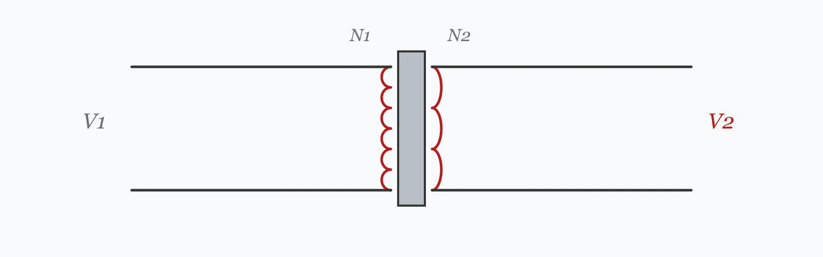
A transformer's turns ratio is simply the primary voltage divided by the secondary. Winding currents follow from the kVA rating divided by each winding's voltage. Enter both voltages, the rating and the efficiency to get all four. Important: these are single-phase relationships — a three-phase transformer's winding currents are lower by a factor of √3.
Calculator
Units:
V
Input winding voltage
V
Output winding voltage at no load
kVA
Nameplate apparent power rating
%
98–99% for distribution units, lower for small transformers
Calculation Result
Press Calculate for the turns ratio, the current in each winding and the output power. The currents assume a single-phase transformer — for a three-phase unit, divide them by √3, about 1.732.
Step-by-Step Solution
Preliminary design aid. Results follow the published formulas cited
below and are intended for estimating, study and early design. Final design must be
verified by a licensed Professional Engineer against the code in force for your project.
Key Benefits
✓Returns turns ratio and both winding currents from four inputs
✓Identifies step-up, step-down and isolation configurations
✓States the three-phase correction explicitly rather than leaving it implicit
✓Shows the losses implied by the efficiency figure
✓Sensitivity chart shows how winding current scales with rating
✓Shareable links and CSV export for electrical design records
What Is Transformer?
A transformer couples two windings through a shared magnetic core. The voltage induced in each is proportional to its number of turns, so the voltage ratio equals the turns ratio: V₁/V₂ = N₁/N₂ = a. Because power is very nearly conserved, current goes the other way — the winding with more turns carries less current. A ratio above 1 is a step-down transformer, below 1 a step-up, and exactly 1 an isolation transformer that changes nothing but the galvanic connection.
kVA rather than kW
Transformers are rated in kVA rather than kW because their limits are thermal, and heating depends on current regardless of its phase relationship to voltage. A transformer supplying a poor power factor load carries full current while delivering less real power, so it is the apparent power that constrains it. The output power figure this calculator returns is the kVA rating reduced by the efficiency, which equals kW only at unity power factor.
The three-phase difference
This calculator applies the single-phase relationship I = kVA·1000/V. A three-phase transformer distributes the same apparent power across three phases, so its line current is kVA·1000/(√3·V) — lower by 73%. The default values here, 11 kV to 415 V at 100 kVA, describe a unit that in practice is always three-phase: the true secondary line current is about 139 A, not the 241 A the single-phase formula returns. Divide by √3 whenever the transformer is three-phase.
Formula
a = V₁ / V₂ = N₁ / N₂
Turns ratio from the primary and secondary voltages
Related Formulas
I = kVA × 1000 / V
I = kVA × 1000 / (√3 × V)
I₁ / I₂ = V₂ / V₁ = 1 / a
P_out = kVA × η × PF
Variable Definitions
Symbol
Variable
Unit
Description
a
Turns Ratio
:1
Primary voltage over secondary. Above 1 is step-down, below 1 step-up.
V₁
Primary Voltage
V
Voltage applied to the input winding.
V₂
Secondary Voltage
V
Voltage delivered by the output winding at no load.
S
kVA Rating
kVA
Apparent power the transformer can deliver continuously without exceeding its temperature rise.
I₁
Primary Current
A
Full-load current in the primary winding, single-phase basis.
I₂
Secondary Current
A
Full-load current in the secondary winding, single-phase basis.
η
Efficiency
%
Fraction of input power delivered. 98% or better for a modern distribution transformer.
How to Use This Calculator
Establish whether the transformer is single or three-phaseThis is the most consequential thing to get right. The calculator returns single-phase currents. For a three-phase unit, divide both currents by √3 — about 1.732. Distribution transformers at 11 kV and above are almost always three-phase.
Use nameplate voltagesTake the rated primary and secondary voltages from the nameplate. The secondary figure is the no-load voltage; under full load it will be lower by the transformer's regulation, typically 2 to 5%.
Enter the kVA rating, not a kW loadTransformers are rated in apparent power because their limit is thermal. A 100 kVA unit supplies 100 kVA regardless of the load's power factor, but only 80 kW of real power at a power factor of 0.8.
Read the output power carefullyThe output figure is the kVA rating multiplied by efficiency. It equals kW only at unity power factor. For a real load, multiply by the power factor as well before treating it as a kW figure.
Use the currents for protection and cable sizingThe winding currents set the protective device ratings and the cable sizes on each side. Remember the primary side also sees an inrush of six to twelve times full-load current at energisation, which protection must ride through.
Worked Examples
Example 1
An 11,000 V to 415 V transformer is rated 100 kVA at 98% efficiency. Find the turns ratio and the winding currents.
Step-by-Step Solution
Turns ratio: a = V₁/V₂ = 11,000 / 415 = 26.51:1 — a step-down transformer
Primary current (single-phase basis): I₁ = 100 × 1000 / 11,000 = 9.09 A
Secondary current (single-phase basis): I₂ = 100 × 1000 / 415 = 240.96 A
Check: the current ratio 240.96 / 9.09 = 26.5, the inverse of the turns ratio, as it must be
Output power: 100 × 0.98 = 98.00 kW at unity power factor, with 2 kW of losses
Now the three-phase correction. An 11 kV / 415 V 100 kVA unit is in practice always three-phase:
I₁ = 100,000 / (√3 × 11,000) = 5.25 A and I₂ = 100,000 / (√3 × 415) = 139.1 A
The three-phase currents are 73% lower. Sizing cables and protection from the single-phase figures would specify roughly twice the copper needed.
Example 2
The same voltages reversed — 415 V to 11,000 V, as in a generator step-up transformer. This shows the relationship working in the other direction.
Step-by-Step Solution
Turns ratio: a = 415 / 11,000 = 0.04:1 — below 1, so a step-up transformer
The currents have simply swapped: the low-voltage winding carries the high current in both cases.
This is the whole basis of power transmission. Delivering 100 kVA at 415 V needs 241 A; at 11 kV it needs 9.09 A.
Since cable losses go as I²R, that 26.5-fold current reduction cuts the transmission loss by a factor of 703 for the same conductor.
It is why the grid transmits at hundreds of kilovolts and steps down only at the point of use — and why the step-up transformer at a generating station is as essential as the generator itself.
Rating Sensitivity
Both winding currents rise linearly with the kVA rating, and their ratio stays fixed at the inverse of the turns ratio. Remember these are single-phase values — divide by 1.732 for a three-phase unit. The marker shows your current rating.
Secondary Current (I₂) vs kVA Rating
Recomputed live from your inputs. The marker shows your current value.
Line chart of Secondary Current (I₂) against kVA Rating. The same
values are listed in the data table below.
Values plotted above, sampled across the kva rating range.
How to Interpret Your Results
The turns ratio tells you the configuration and the currents size the equipment on each side. Read the secondary current first — it is the larger one on a step-down transformer, and the one that sets the switchgear.
Turns Ratio (a): < 1Step-up transformer
A turns ratio of your result:1 is below unity, so the secondary voltage exceeds the primary. The primary winding carries the higher current. This is the generator step-up configuration used at the start of a transmission path.
Turns Ratio (a): 1 – 1.01Isolation transformer
A turns ratio of your result:1 is effectively 1, so this is an isolation transformer. It changes no voltage but separates the two circuits galvanically, which is used for safety, for noise reduction and to establish a separately derived earthing system.
Turns Ratio (a): ≥ 1.01Step-down transformer
A turns ratio of your result:1 reduces the voltage and raises the current on the secondary side. This is the standard distribution configuration, and the secondary is where the switchgear and cabling are sized.
Secondary Current (I₂): ≥ 500High secondary current
A secondary current of your result A on a single-phase basis is substantial, requiring heavy busbar or multiple parallel cables. If the transformer is three-phase, divide by 1.732 first — the real figure may be far more manageable than this suggests.
Output Power: ≥ 500Large transformer
An output of your result kW indicates a substantial unit. At this size, the loss implied by the efficiency figure becomes a real thermal load: verify the cooling arrangement and remember that 2% of a large rating is still a great deal of heat.
Common Mistakes to Avoid
Applying the single-phase current formula to a three-phase transformer
Why it matters:Three-phase line current is kVA·1000/(√3·V), which is 42% of the single-phase result. Using the single-phase figure overstates the current by 73% and specifies roughly twice the copper and switchgear needed.
✓How to avoid it:Divide both currents by √3 for a three-phase unit. Anything at 11 kV or above serving a building is essentially always three-phase.
Treating the kVA rating as a kW capability
Why it matters:A 100 kVA transformer delivers 100 kVA at any power factor, but only 80 kW at a power factor of 0.8. Sizing on kW alone under-specifies the transformer for a reactive load.
✓How to avoid it:Size on apparent power. Divide the real power demand by the expected power factor to obtain the kVA the transformer must supply.
Ignoring inrush current
Why it matters:Energising a transformer draws a magnetising inrush of six to twelve times full-load current, decaying over several cycles. Protection sized on full-load current alone will trip on every energisation.
✓How to avoid it:Select protection with an inrush-tolerant characteristic, or a time delay that rides through the transient while still protecting against a genuine fault.
Using the no-load secondary voltage as the working voltage
Why it matters:The nameplate secondary voltage is at no load. Under full load it drops by the transformer's regulation, typically 2 to 5%, which comes off before any cable volt drop.
✓How to avoid it:Allow for regulation when checking voltage at the load. A 415 V nameplate transformer may deliver 400 V at full load before the distribution cables take their share.
Assuming efficiency is constant across the load range
Why it matters:Transformer efficiency peaks somewhere between half and three-quarter load. Iron losses are constant while copper losses grow with the square of current, so a lightly loaded transformer is inefficient in percentage terms.
✓How to avoid it:Size for the actual load profile rather than the peak. A transformer running at 20% load all year wastes its no-load losses continuously with little useful output to show for it.
Forgetting that losses are continuous
Why it matters:A 100 kVA transformer at 98% efficiency loses 2 kW at full load, and its no-load loss continues whenever it is energised, whether or not anything is drawing power.
✓How to avoid it:Consider no-load losses in any transformer running continuously. Over a 30-year life they frequently exceed the purchase price, which is why efficiency standards for distribution transformers exist.
Practical Applications
▸Sizing distribution transformers for buildings and sites
▸Determining protection ratings on each winding
▸Sizing cables and busbars on both sides
▸Checking turns ratio against nameplate during commissioning
▸Estimating transformer losses for energy accounting
▸Converting between kVA rating and available current
Industry Use Cases
Power distribution
The 11 kV to 415 V step-down transformer is the standard building supply across much of the world. Its rating is chosen from the maximum demand with diversity applied, and the secondary current sets the main switchboard rating, which is usually the larger cost.
Power generation
Generator step-up transformers raise output from generation voltage to transmission voltage. Because transmission losses go as the square of current, the voltage increase is what makes long-distance transmission viable at all — and the transformer is as essential as the generator.
Energy efficiency programmes
No-load losses run continuously for the transformer's entire life, and over 30 years frequently exceed the purchase price. This is why minimum efficiency standards for distribution transformers now exist in most jurisdictions, and why replacing an old unit can pay back on losses alone.
Expert Tips
💡Divide both currents by 1.732 for a three-phase transformer — this is the correction most often missed.
💡Currents are always in the inverse ratio of the voltages; use it as a check on the result.
💡Size on kVA, not kW: a poor power factor load draws full current for less real power.
💡Allow 2 to 5% regulation between the nameplate secondary voltage and full-load delivery.
💡Efficiency peaks between half and three-quarter load, not at full load.
💡No-load losses run whenever the unit is energised, and over 30 years can exceed its purchase price.
Advantages & Limitations
Advantages
✓Gives the turns ratio and both winding currents from nameplate data alone
✓Identifies the configuration automatically from the ratio
✓Currents feed directly into protection and cable sizing
✓Applies to any transformer through its voltage and rating inputs
✓Simple enough to check against a nameplate on site
Limitations
!Uses single-phase relationships; three-phase currents are lower by a factor of √3
!Treats output power as kVA times efficiency, which equals kW only at unity power factor
!Assumes the nameplate no-load secondary voltage, ignoring regulation under load
!Applies one efficiency figure, whereas real efficiency varies with load
!Does not separate no-load from load losses, which behave very differently
!Takes no account of inrush current, which governs protection selection
!Ignores impedance, which determines fault level on the secondary side
Winding Currents, Single-Phase and Three-Phase
The same transformers computed both ways. The three-phase column is what a distribution unit actually carries, and the difference is a factor of 1.732 — enough to change the switchgear rating by two frame sizes.
The calculator returns the single-phase column. Divide by √3 = 1.732 for the three-phase figures shown here.
Divide the primary voltage by the secondary: a = V₁/V₂. An 11,000 V to 415 V transformer has a ratio of 26.51:1. The same ratio applies to the winding turns, and the currents are in the inverse ratio.
How do I convert kVA to amps?
For single-phase, I = kVA × 1000 / V. For three-phase, I = kVA × 1000 / (√3 × V). A 100 kVA transformer at 415 V gives 241 A single-phase but only 139 A three-phase — the distinction matters a great deal.
Why are transformers rated in kVA rather than kW?
Because their limit is thermal, and heating depends on current regardless of its phase relationship to voltage. A transformer supplying a 0.8 power factor load carries full current while delivering only 80% as much real power.
What is the difference between step-up and step-down?
A step-down transformer has a ratio above 1 and reduces voltage while raising current; a step-up does the reverse. Which is which depends only on which winding has more turns, and the same transformer can often be used either way.
How much power does a transformer lose?
A modern distribution unit runs at 98 to 99% efficiency, so a 100 kVA transformer loses around 1 to 2 kW at full load. The no-load component of that continues whenever it is energised, whether or not anything is drawing power.
What is transformer inrush current?
The magnetising surge drawn at energisation, typically six to twelve times full-load current, decaying over several cycles. Protection must ride through it while still detecting a genuine fault, which is why transformer protection uses inrush-tolerant characteristics.
What is voltage regulation?
The drop in secondary voltage between no load and full load, caused by the transformer's own impedance. Typically 2 to 5%, so a 415 V nameplate unit may deliver 400 V at full load before any cable volt drop is counted.
At what load is a transformer most efficient?
Usually between half and three-quarter load, where copper losses — which grow with the square of current — equal the constant iron losses. A heavily oversized transformer running lightly loaded is inefficient in percentage terms.
Why does transmission use high voltage?
Because for a given power, higher voltage means lower current, and losses go as the square of current. Stepping 100 kVA from 415 V to 11 kV cuts the current 26.5-fold and the transmission loss by a factor of 703 for the same conductor.
What does an isolation transformer do?
It has a 1:1 ratio and changes no voltage, but separates the two circuits galvanically. That is used for safety in medical and industrial settings, for noise reduction on sensitive equipment, and to establish a separately derived earthing system.
Glossary
Turns ratio
The ratio of primary to secondary winding turns, equal to the voltage ratio.
kVA
Apparent power, the product of voltage and current, in which transformers are rated.
Step-down transformer
A transformer with more primary than secondary turns, reducing voltage and raising current.
Step-up transformer
A transformer with more secondary than primary turns, raising voltage and reducing current.
Isolation transformer
A 1:1 transformer providing galvanic separation without changing voltage.
Inrush current
The magnetising surge drawn at energisation, six to twelve times full-load current.
Voltage regulation
The fall in secondary voltage from no load to full load, caused by transformer impedance.
No-load loss
The iron loss consumed whenever the transformer is energised, independent of load.
Load loss
The copper loss in the windings, growing with the square of current.
Line current
The current in a supply conductor of a three-phase system, equal to kVA·1000/(√3·V).
Scientific & Standards References
IEC 60076-1 — Power transformers: General — International Electrotechnical Commission
IEEE C57.12.00 — Standard for General Requirements for Liquid-Immersed Distribution, Power and Regulating Transformers — Institute of Electrical and Electronics Engineers
IEC 60076-20 — Energy efficiency requirements for power transformers — International Electrotechnical Commission
EU Regulation 548/2014 — Ecodesign requirements for small, medium and large power transformers — European Commission
Heathcote, M. J., J&P Transformer Book, 13th Edition — Newnes
Conclusion
A transformer's turns ratio is its voltage ratio, and its winding currents follow from the kVA rating divided by each winding voltage — with the currents always in the inverse ratio of the voltages, which is a useful check. The correction that matters most is the phase count: this calculator returns single-phase currents, and a three-phase unit carries 73% less. Its own defaults, 11 kV to 415 V at 100 kVA, describe a transformer that is always three-phase in practice, so the honest secondary current is 139 A rather than 241 A. Two further points are easy to lose: kVA is not kW unless the power factor is unity, and no-load losses run continuously for the life of the unit, often exceeding its purchase price over 30 years.
Try your own transformer above, then sweep the kVA rating in the chart to see both winding currents scale together.