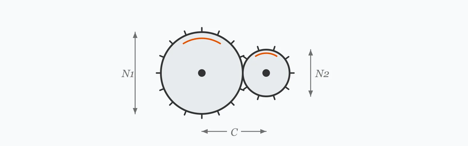
Gear ratio is simply the driven tooth count divided by the driving tooth count. Speed divides by that ratio and torque multiplies by it, less whatever efficiency the mesh loses. Enter the tooth counts, input speed, input torque and efficiency to get all four outputs — and to see how much of the theoretical torque gain survives the losses.
Calculator
Units:
teeth
Input gear tooth count. Below about 17 teeth, undercutting becomes a concern
teeth
Output gear tooth count
RPM
Motor or engine speed at the input shaft
N·m
Torque delivered to the driving gear
%
Spur/helical 97–99, bevel 95–98, worm 40–90
Calculation Result
Press Calculate for the gear ratio, output speed, output torque and mechanical advantage. Output speed follows the ideal ratio; output torque and mechanical advantage include the efficiency you entered.
Step-by-Step Solution
Preliminary design aid. Results follow the published formulas cited
below and are intended for estimating, study and early design. Final design must be
verified by a licensed Professional Engineer against the code in force for your project.
Key Benefits
✓Returns ratio, speed, torque and mechanical advantage in one pass
✓Applies efficiency to torque, so the result is what the shaft actually delivers
✓Distinguishes reduction from overdrive automatically
✓Includes typical efficiency figures for the common gear types
✓Sensitivity chart shows the speed-torque trade across the ratio range
✓Shareable links and CSV export for drivetrain records
What Is Gear Ratio?
When two gears mesh, their teeth must pass the mesh point at the same rate, so the gear with more teeth turns more slowly in exact proportion. The gear ratio is the driven tooth count divided by the driving tooth count: a 20-tooth gear driving a 60-tooth gear gives a ratio of 3:1, and the output shaft turns at one third the input speed. Power is conserved apart from losses, so what is given up in speed reappears as torque.
Reduction and overdrive
A ratio above 1 is a reduction — slower output, more torque — and is what the great majority of drives need, since motors are efficient at high speed and machinery usually is not. A ratio below 1 is an overdrive, trading torque for speed, used where the driven element must outrun its source. The distinction is purely which gear has more teeth.
Where the efficiency goes
No mesh is lossless. Sliding friction between tooth flanks, churning of the lubricant, and bearing and seal drag all consume power. A well-made spur or helical mesh keeps 97 to 99%, a bevel pair 95 to 98%, and a worm drive as little as 40 to 90% depending on lead angle. Because stages multiply, a three-stage box at 97% per stage delivers 0.97³ = 91%, and the heat that represents has to leave the casing somehow.
Formula
GR = N₂ / N₁
Gear ratio from driven and driving tooth counts
Related Formulas
n₂ = n₁ / GR
T₂ = T₁ × GR × η
MA = GR × η
GR_total = GR₁ × GR₂ × GR₃
Variable Definitions
Symbol
Variable
Unit
Description
GR
Gear Ratio
:1
Driven teeth divided by driving teeth. Above 1 is a reduction, below 1 an overdrive.
N₁
Driving Gear Teeth
teeth
Tooth count of the input gear, the one connected to the power source.
N₂
Driven Gear Teeth
teeth
Tooth count of the output gear, connected to the load.
n₁
Input Speed
RPM
Rotational speed of the driving shaft.
T₁
Input Torque
N·m
Torque applied to the driving shaft.
η
Efficiency
%
Fraction of power transmitted through the mesh. 97–99% for spur and helical gears.
How to Use This Calculator
Identify which gear is drivingThe driving gear connects to the power source, the driven gear to the load. Reversing them inverts the ratio, turning a 3:1 reduction into a 0.333:1 overdrive — a mistake that shows up immediately as an output speed three times too high.
Use tooth counts, not diametersTooth counts are exact integers, whereas pitch diameters are derived values that carry rounding. For gears of the same module the ratio is identical either way, but the tooth count is the reliable figure.
Enter a realistic efficiency95% is a reasonable default for a single enclosed mesh. Spur and helical gears reach 97 to 99%, bevel pairs 95 to 98%, and worm drives can fall to 40% at low lead angles. Efficiency affects torque and mechanical advantage but not speed.
Multiply the stages for a compound trainRatios multiply through a gearbox, and so do efficiencies. Three 3:1 stages give 27:1 overall, and three 97% stages give 91% overall — the losses compound just as the ratios do.
Check the practical consequencesThe output torque this returns is what the shaft must carry, so it sizes the output shaft, its bearings and its coupling. High ratios in one stage also mean a large gear, which is often what limits how much reduction a single pair can sensibly deliver.
Worked Examples
Example 1
A motor running at 1,800 RPM and delivering 10 N·m drives a 20-tooth pinion meshing with a 60-tooth gear. The mesh is 95% efficient. Find the output conditions.
Step-by-Step Solution
Gear ratio: GR = N₂/N₁ = 60/20 = 3.000:1 — a speed reduction
Output speed: n₂ = n₁/GR = 1,800/3 = 600.0 RPM
Efficiency as a fraction: η = 95/100 = 0.95
Output torque: T₂ = T₁ × GR × η = 10 × 3 × 0.95 = 28.50 N·m
Mechanical advantage: MA = GR × η = 3 × 0.95 = 2.85
Check the power balance: input = 10 × (2π × 1800/60) = 1,885 W; output = 28.5 × (2π × 600/60) = 1,791 W
The 94 W difference is the 5% lost in the mesh, and it leaves as heat through the casing.
Example 2
Achieving a 27:1 reduction two ways — as a single stage and as three compounded stages. This is where efficiency stops being a footnote.
Step-by-Step Solution
Single stage: a 20-tooth pinion driving a 540-tooth gear gives 27:1
Output torque: 10 × 27 × 0.857 = 231.5 N·m — 25 N·m less than the single stage
So the single stage is more efficient. But a 540-tooth gear at the same module is 27 times the pinion diameter — physically enormous, and requiring a casing to match.
That is the real trade-off in gearbox design: single stages preserve efficiency, multiple stages preserve size. Most commercial reducers above about 6:1 use two or three stages because the packaging constraint wins.
Driven Gear Sensitivity
Torque rises linearly with the driven tooth count while speed falls as its reciprocal — the two curves are mirror images of the same trade. Switch between them to see it. The marker shows your current driven gear.
Output Torque vs Driven Gear Teeth (N₂)
Recomputed live from your inputs. The marker shows your current value.
Line chart of Output Torque against Driven Gear Teeth (N₂). The same
values are listed in the data table below.
Values plotted above, sampled across the driven gear teeth (n₂) range.
How to Interpret Your Results
The gear ratio itself tells you the direction of the trade; the mechanical advantage tells you what actually arrives at the output after losses. The bands below relate the ratio to the arrangements that typically deliver it.
Gear Ratio: < 1Overdrive — speed increase
A ratio of your result:1 is below unity, so the output turns faster than the input and torque falls correspondingly. Overdrives are used where the driven element must outrun its source, and the reduced output torque is the cost.
Gear Ratio: 1 – 6Single-stage reduction range
A ratio of your result:1 is comfortably achievable in one gear pair. Single stages up to about 6:1 are normal for spur and helical gears; beyond that the driven gear becomes awkwardly large relative to the pinion.
Gear Ratio: 6 – 30Usually needs multiple stages
A ratio of your result:1 exceeds what a single spur or helical pair comfortably delivers. Expect two stages, a worm drive, or a planetary arrangement. Remember that stage efficiencies multiply, so a two-stage box at 97% each returns 94%.
A ratio of your result:1 requires three or more stages, a worm drive, or a compound planetary set. Efficiency becomes a significant design factor here: worm drives at high ratios can fall below 50%, and the lost power all becomes heat.
Mechanical Advantage: < 1No torque multiplication
A mechanical advantage of your result means the output torque is at or below the input. Either the drive is an overdrive, or losses have consumed the gain from a near-unity ratio. Verify this is the intended arrangement.
Common Mistakes to Avoid
Reversing the driving and driven gears
Why it matters:The ratio is driven over driving. Swapping them turns a 3:1 reduction into a 0.333:1 overdrive, so the output runs nine times faster than intended relative to the correct value.
✓How to avoid it:The driving gear is the one connected to the motor or engine. If your output speed comes out higher than the input on a reduction drive, this is the reason.
Applying efficiency to the output speed
Why it matters:Efficiency is a power loss, not a speed loss. The kinematic relationship between tooth counts fixes the speed exactly; the losses appear as reduced torque and as heat.
✓How to avoid it:Divide speed by the ratio alone. Apply efficiency only to torque and to power.
Ignoring compounding losses in multi-stage boxes
Why it matters:Stage efficiencies multiply rather than average. Three stages at 95% give 85.7%, not 95%, and the missing 14% appears as heat that the casing has to shed.
✓How to avoid it:Multiply the stage efficiencies. On a large drive, check the resulting heat load against the casing's dissipation capacity before assuming a cooler is unnecessary.
Using a worm drive efficiency figure from a catalogue headline
Why it matters:Worm drive efficiency varies enormously with lead angle and ratio — from around 90% at low ratios to under 40% at high ones. A single quoted figure rarely applies to the ratio you have chosen.
✓How to avoid it:Take the efficiency for your specific ratio from the manufacturer's data. Where the efficiency falls below 50%, the drive is self-locking, which may be a feature or a problem.
Specifying a pinion with too few teeth
Why it matters:Below about 17 teeth for a standard 20-degree pressure angle, the cutter undercuts the tooth root, weakening the tooth and degrading the mesh. It is a manufacturing constraint the ratio calculation does not see.
✓How to avoid it:Keep the pinion at 17 teeth or more, or specify profile shift to avoid undercutting. Where a high ratio forces a small pinion, that is a further argument for splitting the reduction into stages.
Forgetting that the output shaft carries the multiplied torque
Why it matters:A 27:1 reduction multiplies torque 27-fold, and the output shaft, bearings, keys and coupling all have to carry it. Sizing them from the input torque understates the requirement by the full ratio.
✓How to avoid it:Size the output side from the output torque. It is the reason reduction gearboxes have output shafts so much larger than their inputs.
Practical Applications
▸Sizing gearboxes between motors and driven machinery
▸Selecting reduction ratios for conveyors and hoists
▸Designing automotive and bicycle drivetrains
▸Matching pump and fan speeds to their drivers
▸Checking torque capacity of output shafts and couplings
▸Analysing compound gear trains in machine tools
Industry Use Cases
Industrial power transmission
Motors are efficient near 1,500 or 1,800 RPM while most driven machinery wants far less, so nearly every industrial drive contains a reducer. Selection starts from the required output torque and speed, and the ratio follows from what motor is standard.
Automotive engineering
A transmission is a set of selectable ratios letting one engine serve from standstill to cruise. Low gears multiply torque for acceleration; overdrive ratios trade it back for economy once the vehicle is moving.
Robotics and precision motion
Harmonic and cycloidal drives achieve very high ratios in one compact stage with near-zero backlash, which matters more than efficiency in positioning applications. Their efficiency is lower than a gear train, and that is accepted for the precision.
Expert Tips
💡Speed divides by the ratio and torque multiplies by it — that trade is fixed by the tooth counts alone.
💡Efficiency reduces torque, never speed. The lost power leaves as heat.
💡Stage efficiencies multiply: three 95% stages give 85.7%, not 95%.
💡Keep single-stage ratios below about 6:1; beyond that the driven gear grows awkwardly large.
💡Keep pinions at 17 teeth or more to avoid undercutting at a 20-degree pressure angle.
💡Size the output shaft from the multiplied torque, not the input — that is where reduction drives fail.
Advantages & Limitations
Advantages
✓Exact kinematic relationship from integer tooth counts
✓Separates the ideal ratio from the delivered mechanical advantage
✓Extends to compound trains by multiplying stage ratios
✓Applies to spur, helical, bevel and worm gearing alike
✓Fast enough to compare drivetrain options during selection
Limitations
!Covers a single gear pair; compound trains must be multiplied by hand
!Efficiency is entered rather than derived from gear geometry
!Takes no account of tooth strength, contact stress or pitting resistance
!Ignores backlash, which matters in positioning applications
!Does not check for undercutting or interference at low tooth counts
!Assumes steady state; starting torque and shock loads need a service factor
!Does not address lubrication, heat dissipation or noise
Typical Efficiency by Gear Type
Efficiency per stage, and what it compounds to across a three-stage box. The spread is why gear type is chosen for the application rather than by default — a worm drive that self-locks may be worth its losses.
Indicative figures for well-lubricated enclosed drives. Worm efficiency depends strongly on lead angle; below about 50% the drive becomes self-locking.
Divide the driven gear's tooth count by the driving gear's. A 20-tooth pinion driving a 60-tooth gear gives 60/20 = 3:1. The output turns at one third the input speed and delivers roughly three times the torque, less losses.
Does gear ratio increase torque?
A reduction ratio does. Torque multiplies by the ratio while speed divides by it, so power is conserved apart from losses. A 3:1 reduction at 95% efficiency turns 10 N·m into 28.5 N·m.
What is mechanical advantage in a gear train?
The actual torque multiplication achieved, equal to the gear ratio times the efficiency. A 3:1 ratio at 95% efficiency gives a mechanical advantage of 2.85 rather than 3.00.
Does efficiency affect output speed?
No. Speed is fixed by the tooth counts, since teeth must pass the mesh at the same rate. Efficiency losses appear as reduced torque and as heat, never as lost speed.
How do efficiencies combine in a multi-stage gearbox?
They multiply. Three stages at 95% each give 0.95³ = 85.7% overall, not 95%. The compounding is why high-ratio reducers lose more than their per-stage figures suggest.
What is the maximum ratio for a single gear pair?
Around 6:1 for spur gears and up to 10:1 for helical, limited by how large the driven gear becomes relative to the pinion. Worm drives reach 100:1 in one stage but at a substantial efficiency cost.
Why should a pinion have at least 17 teeth?
Below about 17 teeth at a 20-degree pressure angle, the generating cutter undercuts the tooth root, removing material where bending stress is highest. Profile shift can avoid it, but 17 teeth is the practical minimum for a standard tooth form.
What is a compound gear train?
Two or more gear pairs in series, with each stage's output driving the next. Ratios multiply — three 3:1 stages give 27:1 — and so do the efficiencies, which is the trade against a single large stage.
Why are worm drives so inefficient?
Because the worm slides against the wheel teeth rather than rolling, so friction dominates. Efficiency falls with lead angle, reaching below 40% at high ratios. Below about 50% the drive becomes self-locking, which is sometimes exactly what is wanted.
How do I size the output shaft?
From the output torque, not the input. A reduction multiplies torque by the full ratio, so a 27:1 box puts 27 times the input torque into its output shaft, bearings, key and coupling.
Glossary
Gear ratio
The ratio of driven to driving tooth counts, setting the speed and torque relationship between shafts.
Driving gear
The input gear, connected to the motor or engine supplying power.
Driven gear
The output gear, connected to the load.
Reduction
A ratio above 1, decreasing speed and increasing torque.
Overdrive
A ratio below 1, increasing speed and decreasing torque.
Mechanical advantage
The actual torque multiplication delivered, equal to the ratio times the efficiency.
Compound gear train
Multiple gear stages in series, whose ratios and efficiencies both multiply.
Undercutting
Removal of material at the tooth root by the generating cutter when the tooth count is too low.
Backlash
The clearance between meshing teeth, necessary for lubrication but detrimental to positioning accuracy.
Self-locking
A condition, common in high-ratio worm drives, where the output cannot back-drive the input.
Scientific & Standards References
AGMA 2001 — Fundamental Rating Factors and Calculation Methods for Involute Spur and Helical Gear Teeth — American Gear Manufacturers Association
ISO 6336 — Calculation of load capacity of spur and helical gears — International Organization for Standardization
AGMA 6034 — Practice for Enclosed Cylindrical Wormgear Speed Reducers and Gearmotors — American Gear Manufacturers Association
Dudley's Handbook of Practical Gear Design and Manufacture, 3rd Edition — CRC Press
Conclusion
Gear ratio is the driven tooth count over the driving one, and it fixes the speed and torque trade exactly: speed divides, torque multiplies. Efficiency enters only on the torque side — the kinematics are exact, the losses are power and they leave as heat. Two consequences matter in practice. Stage efficiencies multiply rather than average, so a three-stage 95% box returns 85.7%, and that missing power has to be dissipated somewhere. And the output shaft carries the full multiplied torque, which is why reduction gearboxes have output shafts so much heavier than their inputs — sizing that side from the input torque is the failure this calculation is most often used to prevent.
Try your own gear pair above, then sweep the driven tooth count in the chart to watch speed and torque trade against each other.