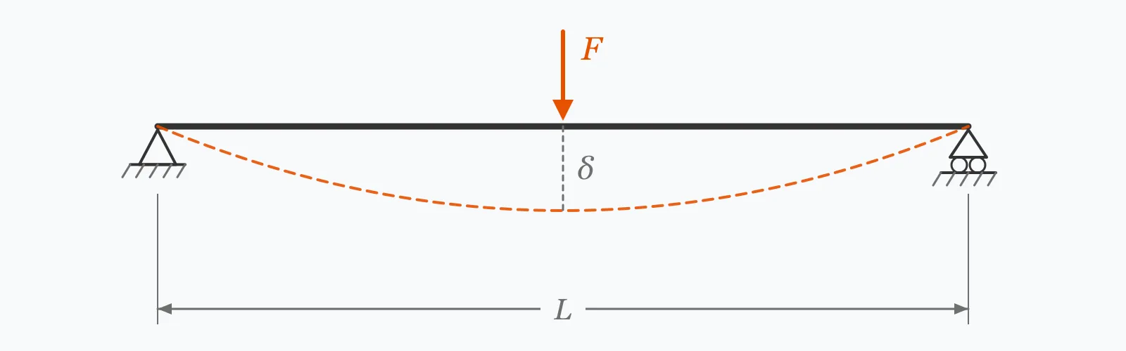
Shaft deflection under a central load is FL³/(48EI), and because I depends on the fourth power of diameter, deflection falls as d⁻⁴. Enter the diameter, span, load and material modulus to get the deflection, the bending stress, the second moment of area and the slope at the bearings — the last of which is what a bearing actually objects to.
Calculator
Units:
mm
Solid shaft diameter
mm
Distance between bearing centres
N
Point load applied at midspan
GPa
Steel 200, aluminium 70, titanium 110, cast iron 120
Calculation Result
Press Calculate for the maximum deflection at midspan, the bending stress there, the second moment of area, and the slope at the supports. Deflection is normally limited to about span/3000, and bearing slope to 0.001 radians.
Step-by-Step Solution
Preliminary design aid. Results follow the published formulas cited
below and are intended for estimating, study and early design. Final design must be
verified by a licensed Professional Engineer against the code in force for your project.
Key Benefits
✓Reports the slope at the supports, which bearings care about more than deflection
✓Gives bending stress alongside deflection, so both checks are visible
✓Makes the fourth-power dependence on diameter explicit
✓Warns against the span/3000 and 0.001 rad limits
✓Sensitivity chart shows how steeply diameter dominates
✓Shareable links and CSV export for design records
What Is Shaft Deflection?
A shaft carrying a load between two bearings behaves as a beam. For a simply supported span with a central point load, the maximum deflection is FL³/(48EI), occurring at midspan. E is the material's Young's modulus and I the second moment of area, which for a solid circular section is πd⁴/64. The bending stress at the same point is the bending moment FL/4 divided by the section modulus πd³/32.
Why stiffness usually governs before strength
A shaft can be perfectly safe in stress and still be unusable. Deflection misaligns whatever it carries: a gear pair whose shafts sag no longer meshes across the full face width, so the tooth load concentrates at one end and the contact stress rises well above the design value. General machinery practice limits deflection to about span/3000, and shafts carrying gears to span/5000 — figures far tighter than any stress criterion would demand.
The slope at the bearings
Deflection at midspan is the number people quote, but the slope at the supports is what the bearings experience. Most rolling and plain bearings tolerate about 0.001 radians of misalignment before the load concentrates on one edge of the raceway and life falls sharply. Self-aligning bearing types exist specifically because this limit is easy to exceed on a long or slender shaft.
Formula
δ = F·L³ / (48·E·I)
Maximum deflection at midspan for a simply supported shaft with a central point load
Related Formulas
I = π·d⁴ / 64
σ = (F·L/4) / (π·d³/32)
θ = F·L² / (16·E·I)
Variable Definitions
Symbol
Variable
Unit
Description
F
Central Load
N
Point load applied at midspan.
L
Span
mm
Distance between bearing centres. Deflection goes with its cube.
d
Shaft Diameter
mm
Solid shaft diameter. Deflection goes inversely with its fourth power.
E
Young's Modulus
GPa
200 for steel, 70 for aluminium, 110 for titanium.
I
Second Moment of Area
mm⁴
πd⁴/64 for a solid circular section.
θ
Support Slope
rad
Angular misalignment presented to the bearings, usually limited to 0.001.
How to Use This Calculator
Use the span between bearing centresNot the overall shaft length. Overhung sections beyond the bearings deflect according to a different formula and are usually worse, since a cantilever of the same length deflects sixteen times as much as a simply supported span.
Place the load where it actually actsThis calculation assumes a central point load, which gives the maximum deflection for a given total load. An off-centre load deflects less, so the central assumption is conservative — and for distributed loads the coefficient changes from 1/48 to 5/384.
Check the slope, not just the deflectionThe slope at the supports is what the bearings experience as misalignment. It is entirely possible to satisfy a deflection limit and exceed 0.001 radians, particularly on a short span with a large load.
Compare against a stiffness limit, not a stress oneSpan/3000 for general machinery and span/5000 where gears are carried. These are much tighter than any stress criterion, which is why shafts are usually sized by stiffness.
Remember what this omitsTorsion acting simultaneously, the shaft's own weight, stress concentration at keyways and shoulders, and critical speed are all separate checks. A rotating shaft also cycles every fibre through full tension and compression each revolution, so fatigue rather than yield governs the stress.
Worked Examples
Example 1
A 30 mm steel shaft spanning 600 mm between bearings, carrying a 2,000 N load at midspan. Young's modulus 200 GPa.
Step-by-Step Solution
Second moment of area: I = π × 30⁴/64 = π × 810,000/64 = 39,761 mm⁴
Slope at supports: FL²/(16EI) = 0.005659 rad, or 0.324°
Interpretation: the stress of 113 MPa is modest for steel, but span/530 is nearly six times the span/3000 limit, and the support slope is 5.7 times the 0.001 rad bearings tolerate. This shaft fails on stiffness while passing comfortably on strength.
Example 2
The same span and load with the diameter increased to 50 mm — the fix that the fourth-power relationship makes so effective.
Step-by-Step Solution
Second moment of area: I = π × 50⁴/64 = 306,796 mm⁴, against 39,761 mm⁴ at 30 mm
That is a factor of 7.72, which is (50/30)⁴ exactly
Deflection: 0.1467 mm, against 1.132 mm — smaller by the same 7.72
Span/deflection: 600/0.1467 = 4,091, comfortably past the span/3000 limit
Slope at supports: 0.000733 rad, now below the 0.001 rad bearing limit
Bending stress: 24.4 MPa, against 113.2 MPa — a factor of only 4.63, because stress goes with d³ rather than d⁴
That difference between the two exponents is the point. Increasing the diameter by 67% improved the stress by a factor of 4.6 and the stiffness by 7.7, so a shaft that was failing stiffness and passing stress is now passing both with room to spare.
It also explains why hollow shafts are so effective. Removing material from the centre, where the bending stress is near zero, costs very little I but saves considerable mass — which matters when the shaft's own weight and its critical speed come into the reckoning.
Diameter Sensitivity
Deflection collapses as diameter grows, because it goes inversely with the fourth power. Bending stress falls only with the cube, so the two curves separate — which is why a shaft can pass on stress and fail on stiffness. The marker shows your current diameter.
Maximum Deflection vs Shaft Diameter
Recomputed live from your inputs. The marker shows your current value.
Line chart of Maximum Deflection against Shaft Diameter. The same
values are listed in the data table below.
Values plotted above, sampled across the shaft diameter range.
How to Interpret Your Results
Deflection relative to the span is the usual acceptance criterion, but the support slope is what determines whether the bearings will survive. Both are stiffness limits, and both are far tighter than the stress check.
Maximum Deflection: < 0.05Very stiff
A deflection of your result mm is small enough to satisfy any normal criterion. Check whether the shaft is heavier than it needs to be — a hollow section removes material from the centre where it contributes least to stiffness.
Maximum Deflection: 0.05 – 0.3Within typical limits
A deflection of your result mm is likely to satisfy the span/3000 general limit. Confirm it against the actual span, and check the support slope separately — the two limits do not always agree.
Maximum Deflection: 0.3 – 1Check against the span
A deflection of your result mm needs comparing against the span. It may be acceptable on a long shaft and excessive on a short one, and if the shaft carries gears the tighter span/5000 limit applies.
Maximum Deflection: ≥ 1Excessive for most machinery
A deflection of your result mm exceeds normal limits unless the span is very long. Increasing the diameter is unusually effective here because deflection goes inversely with the fourth power — a 19% larger shaft halves it.
Slope at Supports: ≥ 0.001Bearing misalignment limit exceeded
A support slope of your result rad exceeds the 0.001 rad most bearings tolerate. Angular misalignment loads one edge of the raceway and shortens bearing life sharply. Either stiffen the shaft or specify self-aligning bearings, which exist for exactly this condition.
Bending Stress: ≥ 100Significant bending stress
A bending stress of your result MPa matters more on a rotating shaft than the figure suggests, because each fibre passes through a full tension-compression cycle every revolution. Fatigue governs, and the endurance limit is well below yield — before any stress concentration at keyways or shoulders is counted.
Common Mistakes to Avoid
Sizing the shaft on stress alone
Why it matters:A shaft can pass a stress check comfortably and still be far too flexible. The worked example carries only 113 MPa — modest for steel — while deflecting to span/530, nearly six times the general limit.
✓How to avoid it:Check deflection and support slope as well. For most machinery shafts, stiffness governs and the stress check is satisfied automatically once it does.
Checking deflection but not the slope at the bearings
Why it matters:They are different quantities with different limits, and a short heavily loaded span can satisfy a deflection criterion while badly exceeding the 0.001 rad bearings tolerate. The bearing fails, not the shaft.
✓How to avoid it:Compute both. Where the slope cannot be reduced, self-aligning ball or spherical roller bearings accommodate it by design.
Using overall shaft length instead of bearing span
Why it matters:The formula applies between supports. Overhung sections beyond a bearing behave as cantilevers, and a cantilever of a given length deflects sixteen times as much as a simply supported span of the same length.
✓How to avoid it:Use the bearing centre distance for this calculation and treat overhangs separately. Overhung loads are usually the more critical case.
Ignoring simultaneous torsion
Why it matters:A shaft transmitting power carries torsional shear at the same time as bending. The combined stress state is what matters, and a shaft satisfactory in bending alone may not be once torsion is superimposed.
✓How to avoid it:Combine bending and torsion using an appropriate failure theory, and remember that a rotating shaft under steady bending experiences fully reversed fatigue loading.
Overlooking stress concentration
Why it matters:Keyways, shoulders, circlip grooves and cross-holes all raise the local stress well above the nominal figure — a sharp shoulder can more than double it. Fatigue failures start at these features almost without exception.
✓How to avoid it:Apply stress concentration factors at every change of section, and use generous fillet radii. The nominal stress this calculator gives is a starting point, not the peak.
Not checking critical speed
Why it matters:Every shaft has a natural frequency at which deflection grows without bound. Running at or near it is destructive regardless of how the static calculation looks, and a flexible shaft has a low critical speed by definition.
✓How to avoid it:Compute the first critical speed and keep the operating speed well clear of it. The same stiffness that limits static deflection also raises the critical speed, so the two goals align.
Practical Applications
▸Sizing machine shafts for stiffness rather than strength
▸Checking bearing misalignment on an existing shaft
▸Assessing gear mesh alignment under load
▸Comparing shaft diameters during design
▸Evaluating the effect of increasing bearing span
▸Screening a design before a full combined-loading analysis
Industry Use Cases
Gearbox design
Shaft deflection is limited far more tightly where gears are carried, commonly to span/5000, because a sagging shaft concentrates the tooth load at one end of the face width. The resulting contact stress can exceed the design value substantially even though the average tooth load is unchanged.
Pumps and rotating machinery
Shaft stiffness governs seal life as well as bearing life, because deflection at the seal face causes uneven wear and leakage. Overhung impeller designs are particularly sensitive, since the cantilever deflection dominates.
Machine tools
Spindle stiffness sets the achievable accuracy directly — any deflection under cutting force becomes a dimensional error in the workpiece. Spindles are therefore sized far above what strength requires, and short bearing spans with large diameters are the norm.
Expert Tips
💡Deflection goes as d⁻⁴, so a 19% larger diameter halves it.
💡Deflection goes as L³, so a 26% longer span doubles it.
💡Stress goes only as d⁻³, which is why stiffness governs before strength.
💡Support slope is limited to about 0.001 rad; deflection to about span/3000.
💡A cantilever deflects sixteen times as much as a simply supported span.
💡Hollow shafts lose little stiffness and save considerable weight.
Advantages & Limitations
Advantages
✓Reports support slope, which is the check most often omitted
✓Gives deflection and stress together, so the governing criterion is visible
✓Makes the difference between the d⁴ and d³ exponents explicit
✓Warns against both stiffness limits rather than only the stress one
✓Simple enough to verify by hand during a design review
Limitations
!Assumes a simply supported shaft with a single central point load
!Does not cover overhung or cantilever sections, which deflect far more
!Ignores the shaft's own weight, significant on long or large shafts
!Takes no account of torsion acting simultaneously
!Gives nominal stress without concentration factors at keyways or shoulders
!Does not compute critical speed, which a flexible shaft is vulnerable to
!Assumes a solid uniform circular section throughout the span
How Diameter Governs Stiffness
A 600 mm span carrying 2,000 N at midspan in steel. Compare how much faster deflection falls than stress — that gap is why shafts are sized by stiffness.
600 mm span, 2,000 N central load, steel at 200 GPa. From 20 to 50 mm the diameter rises 2.5 times, the deflection falls 39.1 times (2.5⁴ = 39.1) and the stress falls only 15.6 times (2.5³ = 15.6). Only the 50 mm shaft satisfies both span/3000 and the 0.001 rad bearing slope limit.
For a simply supported shaft with a central load, δ = FL³/(48EI) with I = πd⁴/64. A 30 mm steel shaft over 600 mm carrying 2,000 N deflects 1.132 mm.
How much does shaft diameter affect deflection?
Enormously — deflection goes inversely with the fourth power of diameter. A 19% increase halves it, and going from 20 mm to 50 mm reduces it by a factor of 39.
What is an acceptable shaft deflection?
About span/3000 for general machinery, and span/5000 where the shaft carries gears. These stiffness limits are far tighter than any stress criterion, which is why shafts are usually sized by stiffness.
What is the slope limit at a bearing?
About 0.001 radians for most rolling and plain bearings. Beyond it the load concentrates on one edge of the raceway and bearing life falls sharply. Self-aligning types exist specifically to accommodate more.
Why is stiffness more critical than strength for shafts?
Because deflection misaligns whatever the shaft carries. A gear mesh, a seal face or a bearing will fail from misalignment long before the steel yields — the worked example carries only 113 MPa while deflecting nearly six times the general limit.
How does span affect deflection?
With its cube. A 26% longer span doubles the deflection, so moving bearings apart is far more damaging to stiffness than it appears. Shortening the span is often easier than enlarging the shaft.
Why do stress and deflection scale differently?
Stress depends on the section modulus, which goes with d³, while deflection depends on the second moment of area, which goes with d⁴. Increasing the diameter therefore improves stiffness faster than it improves strength.
Are hollow shafts stiffer for their weight?
Yes. Material near the centre carries very little bending stress and contributes little to I, so removing it costs a small fraction of the stiffness while saving considerable mass — which also raises the critical speed.
What is critical speed?
The rotational speed matching the shaft's natural frequency, at which deflection grows without bound. A flexible shaft has a low critical speed by definition, so the stiffness that limits static deflection also keeps the critical speed high.
Does this calculation include torsion?
No. A power-transmitting shaft carries torsional shear at the same time as bending, and the combined stress state governs. This gives bending alone, which is the starting point rather than the complete check.
Glossary
Second moment of area
A section property measuring resistance to bending; πd⁴/64 for a solid circle.
Section modulus
I divided by the distance to the extreme fibre; πd³/32 for a solid circle.
Young's modulus
A material's stiffness in tension and bending; 200 GPa for steel.
Simply supported
A beam resting on supports that permit rotation but not vertical movement.
Support slope
The angle the shaft makes at its bearings, seen by them as misalignment.
Critical speed
The rotational speed at which a shaft's natural frequency is excited by rotation.
Stress concentration
Local elevation of stress at a keyway, shoulder or hole.
Fully reversed loading
The tension-compression cycle each fibre of a rotating shaft undergoes every revolution.
Endurance limit
The stress below which steel survives indefinitely under cyclic loading, well below yield.
Self-aligning bearing
A bearing type designed to accommodate angular misalignment between shaft and housing.
Scientific & Standards References
Shigley, J. E. and Mischke, C. R., Mechanical Engineering Design — Chapter on Shafts and Shaft Components — McGraw-Hill
Roark's Formulas for Stress and Strain, 8th Edition — Beams: Deflection and Slope — McGraw-Hill
ISO 281 — Rolling bearings: Dynamic load ratings and rating life (misalignment effects) — International Organization for Standardization
AGMA 6001 — Design and Selection of Components for Enclosed Gear Drives — American Gear Manufacturers Association
Shaft deflection is governed by two exponents that pull in opposite directions for the designer. Span enters as a cube, so moving bearings apart is more damaging than it looks — a 26% longer span doubles the deflection. Diameter enters inversely as a fourth power, so enlarging the shaft is correspondingly effective: a 19% increase halves it. What matters most is that stress scales only with the cube of diameter, so the two criteria separate. The table above shows a 30 mm shaft carrying a modest 113 MPa while deflecting to span/530 — comfortably safe in strength and nearly six times over the stiffness limit. That is the normal situation for machinery shafts, and it is why they are sized by stiffness. The check most often forgotten is the slope at the supports: bearings tolerate about 0.001 radians, and it is entirely possible to satisfy a deflection limit while exceeding it.
Enter your shaft diameter, span and load above to check both stiffness limits.