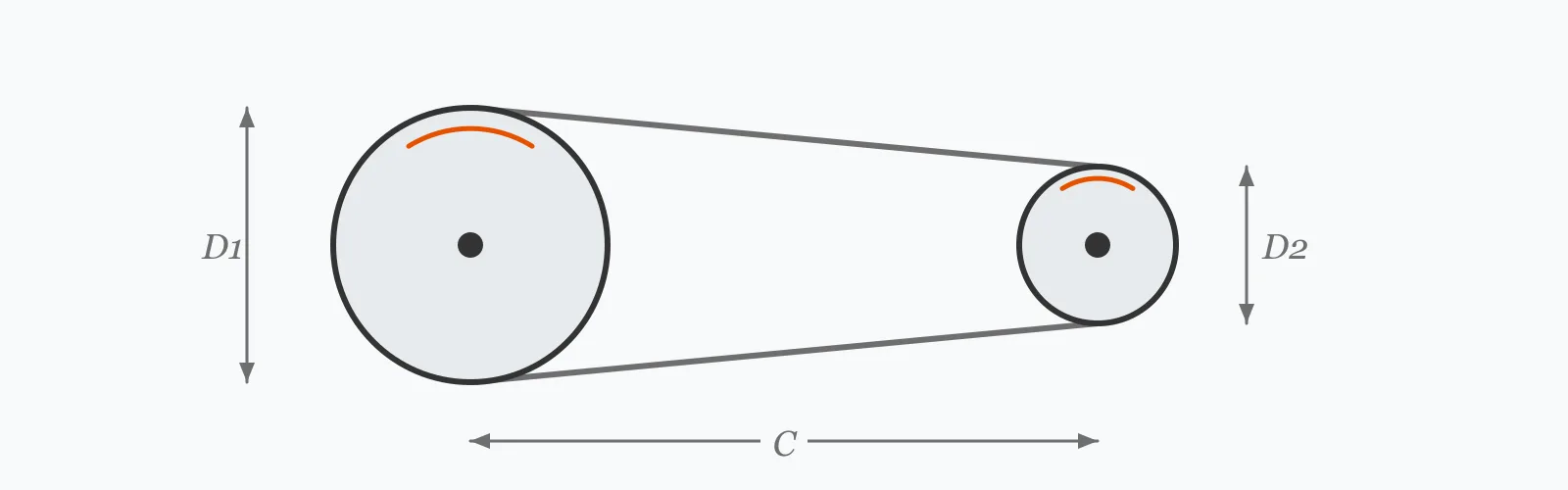
A belt drive's ratio is the driven pulley diameter divided by the driving one. Enter both diameters, the centre distance and the input speed to get the ratio, output speed, belt length and the arc of contact on the small pulley — the last being what determines whether the belt grips or slips.
Calculator
Units:
mm
Pitch diameter on the input shaft
mm
Pitch diameter on the output shaft
mm
Shaft centre to shaft centre. Aim for at least D₁ + D₂
RPM
Speed of the driving shaft
Calculation Result
Press Calculate for the speed ratio, output speed, belt length and contact angle. Read the contact angle first: below 120 degrees the belt is at real risk of slipping under load.
Step-by-Step Solution
Preliminary design aid. Results follow the published formulas cited
below and are intended for estimating, study and early design. Final design must be
verified by a licensed Professional Engineer against the code in force for your project.
Key Benefits
✓Returns ratio, output speed, belt length and contact angle in one pass
✓Warns automatically when the arc of contact falls below 120 degrees
✓Gives the belt length in the form suppliers quote it
✓Includes the centre distance guidance that governs both length and grip
✓Sensitivity chart shows how contact angle responds to centre distance
✓Shareable links and CSV export for drive selection records
What Is Belt Drive?
In an open belt drive, a single belt passes around two pulleys turning in the same direction. Assuming no slip, the belt's linear speed is the same at both pulleys, so their rotational speeds are inversely proportional to their diameters. The speed ratio is therefore the driven diameter over the driving diameter — a 150 mm pulley driving a 300 mm pulley gives 2:1, halving the speed.
Belt length and centre distance
The belt wraps part of each pulley and runs straight between them. Its length is approximately 2C + π(D₁+D₂)/2 + (D₂−D₁)²/4C, where C is the centre distance. Because belts come in standard lengths, the practical sequence is usually the reverse of the calculation: choose a standard belt, then set the centre distance to suit — which is why most drives include an adjustable motor mount.
Why the arc of contact decides everything
A belt transmits power by friction, and how much friction is available depends on how far it wraps the pulley. The smaller pulley always has the smaller arc, so it governs. At 180 degrees, on equal pulleys, the drive is at its most capable. As the ratio rises or the centre distance shrinks, the arc falls, and below about 120 degrees slip becomes likely under load. This is why very high ratios in a single belt stage are impractical.
Formula
i = D₂ / D₁
Speed ratio from driven and driving pulley diameters
Related Formulas
n₂ = n₁ / i
L = 2C + π(D₁+D₂)/2 + (D₂−D₁)²/(4C)
θ = 180° − 2·asin((D₂−D₁)/2C)
T₁/T₂ = e^(μθ)
Variable Definitions
Symbol
Variable
Unit
Description
i
Speed Ratio
:1
Driven diameter divided by driving diameter. Above 1 reduces speed.
D₁
Driving Pulley Diameter
mm
Pitch diameter of the pulley on the motor or input shaft.
D₂
Driven Pulley Diameter
mm
Pitch diameter of the pulley on the load shaft.
C
Centre Distance
mm
Distance between the two shaft centres. Sets both belt length and arc of contact.
L
Belt Length
mm
Pitch length of the belt required for the geometry.
θ
Arc of Contact
°
Angle of wrap on the smaller pulley. Below 120° slip becomes likely.
How to Use This Calculator
Use pitch diameters, not outside diametersFor V-belts the pitch diameter is where the belt's neutral axis sits in the groove, slightly below the outside diameter. Manufacturers' tables give it, and using the outside diameter introduces a small ratio error.
Set a sensible centre distanceA common guide is at least D₁ + D₂ and no more than about three times that. Too short and the arc of contact collapses; too long and the belt whips, especially on the slack side at high speed.
Read the contact angle before anything elseBelow 120 degrees, slip is likely under load. The fix is a longer centre distance, a smaller ratio, or an idler pulley pressing on the slack side to increase the wrap.
Round the belt length to a standard sizeBelts come in standard pitch lengths. Choose the nearest and then adjust the centre distance to suit, which is why nearly every belt drive has slotted motor feet or a tensioning rail.
Apply the capacity correctionsManufacturers' power ratings assume 180 degrees of wrap and a nominal belt length. Apply their arc-of-contact and length correction factors, plus a service factor for the driven machine, before deciding how many belts you need.
Worked Examples
Example 1
A 150 mm driving pulley on a 1,750 RPM motor drives a 300 mm pulley at a 500 mm centre distance. Find the ratio, output speed, belt length and contact angle.
Assessment: 162.7 degrees is comfortably above the 120-degree threshold, so grip is not a concern. Select the nearest standard belt to 1,718 mm and set the centre distance to suit.
Example 2
The same pulleys pushed into a tight installation with the centre distance reduced from 500 mm to 200 mm. This is where the arc of contact becomes the binding constraint.
Step-by-Step Solution
Ratio and output speed are unchanged: 2.000:1 and 875.0 RPM, since they depend only on the diameters
Belt length: L = 2(200) + 706.86 + (150)²/(800) = 400 + 706.86 + 28.13 = 1,135 mm
Comparison: the arc fell from 162.7° to 136.0° — still above the 120° threshold, but the margin has shrunk considerably
Push the centre distance to 150 mm and the arc falls to about 120°, at which point slip under load becomes a real risk.
The remedies, in order of preference: lengthen the centre distance, split the ratio across two stages, or fit an idler on the slack side to increase the wrap. An idler is the usual answer when the layout cannot change.
Centre Distance Sensitivity
Contact angle rises steeply at short centre distances then flattens towards 180 degrees, while belt length grows linearly. The knee is where extra centre distance stops improving grip and only adds belt. The marker shows your current centre distance.
Contact Angle (small pulley) vs Center Distance (C)
Recomputed live from your inputs. The marker shows your current value.
Line chart of Contact Angle (small pulley) against Center Distance (C). The same
values are listed in the data table below.
Values plotted above, sampled across the center distance (c) range.
How to Interpret Your Results
The arc of contact on the smaller pulley is the number that decides whether a belt drive works. It is where the available friction comes from, and it is the first thing a manufacturer's capacity table corrects for.
An arc of contact of your result° is below the 120-degree threshold at which belt drives become unreliable. There is not enough wrap to generate the friction the drive needs. Increase the centre distance, reduce the ratio, or fit an idler pulley on the slack side.
An arc of contact of your result° works but is reduced. Manufacturers' power ratings assume 180 degrees, so apply their arc-of-contact correction — at 140 degrees it typically costs around 11% of the rated capacity.
Contact Angle (small pulley): 150 – 180Good wrap
An arc of contact of your result° gives good grip on the smaller pulley. The correction against the 180-degree rating is small, and slip should not be a concern at normal service factors.
Speed Ratio: ≥ 6High ratio for a single belt stage
A ratio of your result:1 is high for one belt stage. Large ratios shrink the arc of contact on the small pulley and demand a large driven pulley. Above about 6:1, splitting across two stages or using a gear reducer is usually the better arrangement.
Belt Length: ≥ 4000Long belt — check for whip
A belt length of your result mm is substantial. Long spans between pulleys are prone to whipping on the slack side at speed, which causes noise, vibration and accelerated wear. A guide idler on the slack span is the usual remedy.
Common Mistakes to Avoid
Using outside diameter instead of pitch diameter
Why it matters:A V-belt sits down in its groove, so its effective diameter is smaller than the pulley's outside diameter. Using the outer figure gives a ratio error of a few percent — small, but it shows up as an unexpected output speed.
✓How to avoid it:Take pitch diameters from the manufacturer's data. For flat belts the difference is negligible; for V-belts in small pulleys it is not.
Ignoring the arc of contact
Why it matters:Power capacity depends on how far the belt wraps the small pulley. A drive sized on the rated capacity but installed at 130 degrees of wrap is overloaded by more than 10% before it starts.
✓How to avoid it:Read the contact angle and apply the manufacturer's arc-of-contact correction factor. Below 120 degrees, redesign the geometry rather than correcting for it.
Setting the centre distance too short
Why it matters:It collapses the arc of contact on the small pulley, and it also increases how often each point on the belt passes through a bend, which shortens fatigue life.
✓How to avoid it:Keep the centre distance at or above D₁ + D₂ where the layout allows. Where it cannot be, use an idler to restore the wrap.
Forgetting the service factor
Why it matters:Belt power ratings are for smooth, continuous duty. A driven machine with shock loading, frequent starts or long daily running needs substantially more capacity than its nominal power suggests.
✓How to avoid it:Apply the service factor from the manufacturer's tables — commonly 1.0 to 1.8 depending on the driven machine and hours of operation — before selecting the belt count.
Over-tensioning to stop slip
Why it matters:Excessive tension is the most common cause of premature bearing failure in belt drives. It also stretches the belt and does nothing about an inadequate arc of contact, which is usually the real cause.
✓How to avoid it:Tension to the manufacturer's deflection specification. If the drive still slips, the geometry or the belt count is wrong — more tension will not fix it.
Assuming no slip in the speed calculation
Why it matters:Real belt drives creep by 1 to 2% under load as the belt stretches and relaxes around the pulleys. Where output speed matters precisely, that error is not negligible.
✓How to avoid it:Allow 1 to 2% below the calculated output speed for a friction belt drive. Where exact speed is required, use a toothed synchronous belt or gears instead.
Practical Applications
▸Selecting pulleys and belts for motor-driven machinery
▸Setting fan and pump speeds without a gearbox
▸Designing machine tool spindle drives
▸Checking existing drives after a motor or pulley change
▸Determining belt length for procurement
▸Assessing whether an idler is needed to restore wrap
Industry Use Cases
HVAC and building services
Fan speeds are trimmed by changing pulley diameters rather than the motor, which is why adjustable-pitch pulleys are standard on air handling units. A small diameter change fine-tunes the airflow without touching the electrical installation.
Industrial machinery
Belt drives are chosen over gears where slip is a feature: the belt acts as a mechanical fuse, protecting the driven machine and the motor from a jam. On crushers and conveyors handling unpredictable material, that protection is worth the efficiency loss.
Maintenance and reliability
Belt drives are among the most frequently mis-tensioned components in a plant. Over-tensioning to cure a slip that is actually a wrap or service factor problem is the leading cause of premature bearing failure on driven equipment.
Expert Tips
💡Read the arc of contact before the ratio — it is what decides whether the drive grips.
💡Below 120 degrees of wrap, fix the geometry rather than adding tension.
💡Keep the centre distance at or above D₁ + D₂ where the layout allows.
💡Belts come in standard lengths, so pick the belt first and adjust the centre distance to suit.
💡Allow 1 to 2% slip in the output speed of any friction belt drive.
💡An idler on the slack side increases wrap and damps whip — the standard fix for a cramped layout.
Advantages & Limitations
Advantages
✓Gives ratio, length and wrap from four readily available inputs
✓Flags the contact angle problem automatically
✓Belt length is returned in the form suppliers quote
✓Applies to flat and V-belt drives alike
✓Fast enough to compare layouts during design
Limitations
!Covers open belt drives only, not crossed belts or multi-pulley arrangements
!Assumes no slip, whereas real drives creep by 1 to 2% under load
!Does not compute power capacity, which needs the manufacturer's rating tables
!Omits the arc-of-contact, belt length and service factor corrections
!Uses the approximate belt length expression, adequate for normal geometries
!Takes no account of belt tension, which must be set to the manufacturer's specification
!Does not address belt speed limits, which govern at high pulley speeds
Contact Angle by Centre Distance
A 150 mm pulley driving a 300 mm pulley at various centre distances. The arc rises steeply at first and then flattens, so beyond about twice the pulley sum the extra distance buys mostly belt.
Open belt drive, D₁ = 150 mm, D₂ = 300 mm. Contact angle approaches but never reaches 180° for unequal pulleys.
Divide the driven pulley diameter by the driving pulley diameter. A 150 mm pulley driving a 300 mm pulley gives 2:1, so the output turns at half the input speed. Use pitch diameters rather than outside diameters for V-belts.
How do I calculate belt length?
L = 2C + π(D₁+D₂)/2 + (D₂−D₁)²/4C, where C is the centre distance. For 150 and 300 mm pulleys at 500 mm centres, that gives 1,718 mm. Round to the nearest standard belt and adjust the centre distance.
What is the arc of contact and why does it matter?
It is how far the belt wraps around the smaller pulley. Since belts transmit power by friction, more wrap means more grip. Manufacturers rate belts at 180 degrees, and apply a reduction factor below that.
What is the minimum contact angle for a belt drive?
About 120 degrees. Below that, there is not enough wrap to generate the necessary friction and slip becomes likely under load. Increase the centre distance, reduce the ratio, or add an idler on the slack side.
What centre distance should I use?
A common guide is at least the sum of the two pulley diameters, and no more than about three times that. Too short collapses the arc of contact; too long allows the slack side to whip at speed.
Do belt drives slip?
All friction belt drives creep by 1 to 2% under load as the belt stretches and relaxes around each pulley. Gross slip only occurs when the drive is overloaded, under-tensioned or short of wrap. For exact speed, use a toothed synchronous belt.
What is the maximum ratio for a single belt stage?
About 6:1 in practice. Higher ratios shrink the arc of contact on the small pulley and demand a driven pulley large enough to become awkward. Beyond that, use two stages or a gear reducer.
How tight should a belt be?
To the manufacturer's deflection specification — typically a defined force producing a defined deflection at the span midpoint. Over-tensioning is the leading cause of premature bearing failure in belt-driven equipment.
Why does my belt squeal?
Almost always slip, from insufficient tension, insufficient wrap, an overload, or contamination on the pulley faces. Check the arc of contact and the service factor before simply tightening — tension rarely fixes a geometry problem.
Are belt drives more or less efficient than gears?
Slightly less. A well-tensioned V-belt drive runs at 94 to 98% against 97 to 99% for a gear mesh. Belts win on cost, on tolerance of misalignment, on quietness, and on their ability to slip under overload rather than break something.
Glossary
Speed ratio
The ratio of driven to driving pulley diameter, setting the speed relationship between shafts.
Pitch diameter
The effective diameter at which a belt's neutral axis runs, slightly below the pulley outside diameter for V-belts.
Centre distance
The distance between the two shaft centres, which governs both belt length and arc of contact.
Arc of contact
The angle over which the belt wraps a pulley, determining the friction available for power transmission.
Idler pulley
An additional pulley pressing on the slack span to increase wrap, take up slack or damp whip.
Slack side
The belt span with lower tension, on the leaving side of the driving pulley.
Creep
The small speed loss, typically 1 to 2%, caused by belt stretch and relaxation around the pulleys.
Service factor
A multiplier applied to transmitted power to allow for shock loading and duty cycle.
Synchronous belt
A toothed belt engaging matching pulley grooves, eliminating slip at the cost of noise and misalignment tolerance.
ISO 4184 — Belt drives: Classical and narrow V-belts, lengths in datum system — International Organization for Standardization
RMA IP-20 — Specifications for Drives Using Classical V-Belts — Rubber Manufacturers Association
ISO 5292 — Belt drives: V-belts and V-ribbed belts, calculation of power ratings — International Organization for Standardization
Gates Design Manual for Industrial Power Transmission Belt Drives — Gates Corporation
Conclusion
A belt drive's ratio comes from the pulley diameters and its belt length from the geometry, but the number that determines whether it works is the arc of contact on the smaller pulley. Friction is what transmits the power, and wrap is what provides the friction — below about 120 degrees the drive will slip under load whatever tension is applied. Two habits follow. Read the contact angle before the ratio, and fix a slipping drive by changing geometry or belt count rather than by tightening, since over-tensioning is the leading cause of premature bearing failure in belt-driven equipment. And remember the ratio is nominal: all friction drives creep 1 to 2%, so where exact speed matters, the answer is a toothed belt.
Try your own drive above, then sweep the centre distance in the chart to see where extra distance stops improving grip.