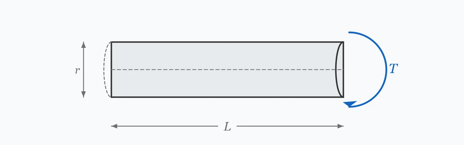
A circular shaft under torque develops shear stress τ = Tr/J, greatest at the outer surface, and twists through an angle θ = TL/(JG). Enter the torque, diameter, length and shear modulus to get both. Because the polar moment of inertia goes as the fourth power of diameter, a small increase in shaft size has a large effect on both stress and twist.
Calculator
Units:
N·m
Twisting moment about the shaft axis
mm
Outer diameter — stress falls with its cube, twist with its fourth power
m
Length over which the twist accumulates
GPa
Steel ≈ 79, aluminium ≈ 26, titanium ≈ 44 GPa
Calculation Result
Press Calculate for the maximum shear stress at the outer surface and the total angle of twist over the shaft length. Compare the stress against the allowable shear for your material, and the twist against the stiffness requirement for the application.
Step-by-Step Solution
Preliminary design aid. Results follow the published formulas cited
below and are intended for estimating, study and early design. Final design must be
verified by a licensed Professional Engineer against the code in force for your project.
Key Benefits
✓Returns both the strength check and the stiffness check in one pass
✓Makes the fourth-power effect of diameter immediately visible
✓Reports twist in degrees, the form specifications are usually written in
✓Includes the hollow shaft comparison showing where the material earns its place
✓Sensitivity chart shows how sharply stress and twist fall as diameter grows
✓Shareable links and CSV export for design records
What Is Torsion & Shear Stress?
When a circular shaft is twisted, each cross-section rotates relative to its neighbour while remaining plane and circular. Shear strain grows linearly from zero at the axis to a maximum at the outer surface, and with a linear elastic material the shear stress follows the same distribution: τ = Tr/J, where r is the radius at the point of interest and J the polar moment of inertia. For a solid circular shaft, J = πD⁴/32.
Why diameter dominates so completely
The polar moment of inertia goes as the fourth power of diameter, while the radius in the numerator goes as the first — so maximum stress falls with the cube of diameter and twist falls with the fourth power. Increasing a 50 mm shaft to 60 mm reduces peak stress from 20.37 to 11.79 MPa, a 42% drop, and the twist from 1.18 to 0.57 degrees, a 52% drop. Both for 44% more material by weight.
Why only circular sections behave this simply
The assumption that plane sections remain plane holds exactly for a circular shaft and for no other shape. A rectangular bar under torque warps out of plane, its shear stress peaks at the middle of the long side rather than at the corners, and its torsional constant is found from empirical coefficients rather than a closed form. Open sections such as I-beams and channels are dramatically weaker in torsion than closed ones of the same area, which is why torsionally loaded members are made from tubes.
Formula
τ_max = T·r / J
Maximum torsional shear stress at the outer surface of a circular shaft
Related Formulas
J = πD⁴ / 32
θ = T·L / (J·G)
J = π(D⁴ − d⁴) / 32
P = T·ω
Variable Definitions
Symbol
Variable
Unit
Description
τ_max
Maximum Shear Stress
MPa
Peak shear stress, occurring at the outer surface where the radius is greatest.
T
Applied Torque
N·m
Twisting moment applied about the shaft axis.
r
Outer Radius
mm
Distance from the axis to the outer surface, half the diameter.
J
Polar Moment of Inertia
mm⁴
Torsional equivalent of the second moment of area; πD⁴/32 for a solid circle.
θ
Angle of Twist
degrees
Total relative rotation between the two ends of the shaft.
L
Shaft Length
m
Length over which the twist accumulates. Twist is directly proportional to it.
G
Shear Modulus
GPa
Material stiffness in shear. Steel is about 79 GPa, aluminium 26 GPa.
How to Use This Calculator
Enter the torque in newton-metresFor a rotating shaft, torque follows from power and speed as T = P/ω, where ω is in radians per second. A 10 kW motor at 1,450 rpm delivers about 65.9 N·m.
Use the outer diameterPeak stress occurs at the outer surface, so the outer diameter sets both J and the radius in the numerator. This calculator covers solid shafts; for a hollow one, use J = π(D⁴ − d⁴)/32 by hand.
Enter the length over which twist accumulatesUse the distance between the point where torque is applied and where it is reacted. Twist is directly proportional to this length, so a long shaft twists proportionally more for the same stress.
Enter the shear modulus, not Young's modulusTorsion depends on shear stiffness G, roughly 0.385 times E for most metals. Steel is about 79 GPa against 200 GPa in tension. Substituting E would understate the twist by a factor of about 2.5.
Check both results against their own limitsCompare the stress against the allowable shear — commonly 0.4 to 0.6 of tensile yield for static design. Compare the twist against the application's requirement, often quoted as degrees per metre for power transmission shafts.
Worked Examples
Example 1
A solid steel shaft 50 mm in diameter and 2.0 m long transmits a torque of 500 N·m. The shear modulus is 79 GPa. Find the maximum shear stress and the angle of twist.
Step-by-Step Solution
Polar moment of inertia: J = πD⁴/32 = π × 50⁴ / 32 = π × 6,250,000 / 32
J = 613,592 mm⁴
Outer radius: r = D/2 = 25 mm
Convert torque to consistent units: T = 500 N·m = 500,000 N·mm
Convert for the twist: L = 2.0 m = 2,000 mm; G = 79 GPa = 79,000 MPa
Angle of twist: θ = TL/(JG) = 500,000 × 2,000 / (613,592 × 79,000) = 0.02063 rad
In degrees: 0.02063 × 180/π = 1.18°, or 0.59 degrees per metre
Assessment: 20.37 MPa is far below the allowable shear of structural steel, so this shaft is governed by stiffness rather than strength if the application has a twist limit.
Example 2
The same torque, length and material, but the diameter increased from 50 mm to 60 mm — a 20% change. This shows the fourth-power effect at work.
Step-by-Step Solution
Polar moment of inertia: J = π × 60⁴ / 32 = π × 12,960,000 / 32 = 1,272,345 mm⁴
That is 2.07 times the value for the 50 mm shaft, from a 20% diameter increase
Angle of twist: θ = 500,000 × 2,000 / (1,272,345 × 79,000) = 0.00995 rad = 0.57°
Comparison: stress fell 42% and twist fell 52%, for a mass increase of only 44%
The scaling explains it: stress goes as 1/D³, so (50/60)³ = 0.579; twist goes as 1/D⁴, so (50/60)⁴ = 0.482. Both match the computed reductions.
Design conclusion: where a shaft fails on torsion, increasing diameter is dramatically more effective than changing material — no common engineering alloy offers a 42% higher shear modulus.
Diameter Sensitivity
Shear stress falls with the cube of diameter and twist with the fourth power, so both curves drop steeply and then flatten into a long tail. Switch between them to compare the two rates. The marker shows your current diameter.
Max Shear Stress vs Diameter (D)
Recomputed live from your inputs. The marker shows your current value.
Line chart of Max Shear Stress against Diameter (D). The same
values are listed in the data table below.
Values plotted above, sampled across the diameter (d) range.
How to Interpret Your Results
Torsional design has two independent checks, and they are governed by different things. Stress must stay below the material's allowable shear; twist must stay within whatever the application tolerates, which for precision machinery can be far tighter than any strength limit.
Max Shear Stress: < 40Low shear stress
A maximum shear stress of your result MPa is comfortably below the allowable shear of structural and machinery steels, which typically runs from 80 to 150 MPa. Strength is not the constraint here — check the angle of twist, which is more likely to govern.
Max Shear Stress: 40 – 100Moderate shear stress
A maximum shear stress of your result MPa sits in the normal working range for steel shafts. Confirm it against the allowable shear for your specific grade and, where the shaft rotates under reversing load, check the fatigue limit rather than the static one.
Max Shear Stress: 100 – 200High shear stress
A maximum shear stress of your result MPa approaches the allowable limit for many steels. Verify against your material's yield in shear, and pay close attention to stress concentrations at keyways, splines and shoulder fillets, which can double the local stress.
Max Shear Stress: ≥ 200Very high shear stress
A maximum shear stress of your result MPa exceeds the allowable shear of most engineering steels. Increase the diameter — stress falls with its cube, so even a modest increase helps substantially — or reduce the torque.
Angle of Twist: ≥ 3Large angle of twist
A twist of your result degrees is substantial. Power transmission shafts are commonly limited to around 0.25 degrees per metre, and precision drives to far less. Twist falls with the fourth power of diameter, so a small increase in shaft size is the efficient remedy.
Common Mistakes to Avoid
Using Young's modulus instead of the shear modulus
Why it matters:Torsion depends on shear stiffness G, not tensile stiffness E. For steel, G is about 79 GPa against 200 GPa, so substituting E understates the angle of twist by a factor of roughly 2.5.
✓How to avoid it:Use G, approximately E/2(1+ν), which works out to about 0.385E for most metals. Steel 79 GPa, aluminium 26 GPa, titanium 44 GPa.
Applying circular shaft theory to a non-circular section
Why it matters:The assumption that plane sections remain plane holds only for circles. A rectangular bar warps under torque, its stress peaks at the middle of the long side rather than the corners, and its torsional constant is far lower than the polar moment of inertia would suggest.
✓How to avoid it:Use the appropriate torsional constant J for the shape from a reference table. For open sections such as I-beams and channels, torsional stiffness is a small fraction of a closed section of equal area.
Ignoring stress concentrations at keyways and fillets
Why it matters:A keyway, spline or shoulder fillet raises the local stress well above the nominal value — a factor of 2 to 3 is common at a sharp keyway. Shaft failures almost always start at these features.
✓How to avoid it:Apply the appropriate stress concentration factor from a reference such as Peterson's, and specify generous fillet radii. A larger radius is the cheapest strength improvement available.
Designing a rotating shaft on static strength alone
Why it matters:A rotating shaft under a bending load experiences fully reversed stress every revolution, so fatigue rather than static yield governs. The endurance limit can be less than half the static allowable, and lower still with a surface notch.
✓How to avoid it:Use a fatigue design method — the Soderberg or Goodman approach with the relevant surface, size and stress concentration factors — for any shaft that rotates under load.
Checking stress but not twist
Why it matters:A shaft can be perfectly safe in strength and still be unusable. Excessive twist causes timing errors in drivetrains, positional error in machinery, and torsional vibration in long shafts.
✓How to avoid it:Check both. Power transmission shafts are commonly limited to about 0.25 degrees per metre, and precision positioning drives to considerably less.
Overlooking combined bending and torsion
Why it matters:Most real shafts carry bending from gears, pulleys or belt tension at the same time as torque. Checking either alone understates the combined stress state substantially.
✓How to avoid it:Use an equivalent stress approach — the maximum shear stress or von Mises criterion — combining the bending and torsional components before comparing against the allowable.
Practical Applications
▸Sizing drive shafts for motors, gearboxes and pumps
▸Checking torsional stiffness in machine tool spindles
▸Verifying torque tube capacity in vehicles and aircraft
▸Assessing structural members subject to eccentric loading
▸Designing torsion bar springs and anti-roll bars
▸Checking twist in long transmission and propeller shafts
Industry Use Cases
Mechanical power transmission
Drive shafts are sized from motor torque and then checked against a twist limit, commonly 0.25 degrees per metre. Because twist falls with the fourth power of diameter, the stiffness requirement usually sets the shaft size long before the stress limit does.
Automotive engineering
Torsion bars and anti-roll bars are designed to twist by a controlled amount rather than to resist it, so the same formulas run in reverse — the target rate sets the diameter, and the resulting stress is checked afterwards against the fatigue limit.
Structural steelwork
Beams loaded eccentrically develop torsion, and open sections resist it very poorly. Engineers typically avoid designing for torsion at all, restraining the member or using a closed hollow section instead — a tube can be a hundred times stiffer in torsion than an I-section of the same area.
Expert Tips
💡Diameter is overwhelmingly the most effective variable: stress falls with its cube, twist with its fourth power.
💡A hollow shaft loses little torsional capacity for a large weight saving, because material near the axis carries almost no stress.
💡Use G, not E — around 0.385E for common metals, and about 79 GPa for steel.
💡Check twist per metre rather than total twist; it is the form specifications are normally written in.
💡Generous fillet radii at shoulders are the cheapest available improvement in fatigue life.
💡For any structural member expected to carry torsion, use a closed hollow section — open sections are dramatically weaker.
Advantages & Limitations
Advantages
✓Exact closed-form solution for a circular shaft, the case it applies to
✓Delivers both the strength and stiffness checks from the same four inputs
✓Reports twist in degrees, matching how specifications are written
✓Extends directly to hollow shafts by substituting the appropriate J
✓Simple enough to verify by hand during a design review
Limitations
!Valid for solid circular sections only; other shapes need their own torsional constant
!Assumes linear elastic behaviour with no yielding
!Takes no account of stress concentrations at keyways, splines, holes and fillets
!Ignores fatigue, which governs any shaft rotating under load
!Does not combine torsion with bending or axial force, which real shafts usually carry together
!Assumes a prismatic shaft of constant diameter along its length
!Omits torsional vibration and critical speed, which matter for long or fast-rotating shafts
Solid Versus Hollow Shafts of Equal Outer Diameter
Material near the axis carries almost no torsional stress, so removing it costs far less capacity than weight. This is the case for hollow shafts in every weight-sensitive application.
Polar moment of inertia for a 50 mm outer diameter shaft with varying bore. Capacity is proportional to J; mass is proportional to cross-sectional area.
Use τ = Tr/J, where T is the applied torque, r the outer radius and J the polar moment of inertia, equal to πD⁴/32 for a solid circular shaft. A 500 N·m torque on a 50 mm shaft gives 20.37 MPa at the surface.
What is the polar moment of inertia?
The torsional equivalent of the second moment of area, describing how a section resists twisting. For a solid circle it is πD⁴/32; for a hollow one, π(D⁴ − d⁴)/32. Its fourth-power dependence on diameter is why shaft size matters so much.
How do I calculate the angle of twist?
θ = TL/(JG) gives the twist in radians, which multiplied by 180/π converts to degrees. Note that G is the shear modulus, about 79 GPa for steel — using Young's modulus instead would understate the twist by a factor of 2.5.
Where is torsional stress greatest in a shaft?
At the outer surface, where the radius is largest. Stress varies linearly from zero at the axis to the maximum at the surface, which is exactly why hollow shafts are efficient — the removed material was barely working.
Why is diameter so effective in torsion?
Because J grows with the fourth power of diameter while the radius in the numerator grows with the first. Net effect: stress falls with the cube of diameter and twist with the fourth power. Going from 50 to 60 mm cuts stress 42% and twist 52%.
How much capacity does a hollow shaft lose?
Far less than the weight it saves. A 50 mm shaft bored to 30 mm keeps 87% of its torsional capacity while shedding 36% of its mass. Material near the axis carries almost no stress, so removing it costs little.
What is an acceptable angle of twist?
It depends on the application. Power transmission shafts are commonly limited to about 0.25 degrees per metre; precision positioning drives require far less; torsion bar springs are designed to twist by many degrees deliberately.
Can I use these formulas for a rectangular bar?
No. Non-circular sections warp out of plane under torque, so the simple theory breaks down. Rectangular bars use empirical coefficients, their peak stress occurs at the middle of the long side, and their torsional constant is much lower than the polar moment of inertia would suggest.
What is the shear modulus of steel?
About 79 GPa (11,500 ksi) for structural and machinery steels. It relates to Young's modulus as G = E/2(1+ν), which with a Poisson's ratio of 0.3 gives roughly 0.385E. Aluminium is about 26 GPa and titanium 44 GPa.
Do I need to check fatigue on a shaft?
For any shaft that rotates under load, yes. Rotation reverses the bending stress every revolution, so fatigue rather than static yield governs. The endurance limit can be under half the static allowable, and lower again with a keyway or a sharp fillet.
Glossary
Torsion
Twisting of a member about its longitudinal axis under an applied moment.
Torque (T)
The twisting moment applied about the axis of a shaft.
Polar moment of inertia (J)
The section property describing resistance to twisting, equal to πD⁴/32 for a solid circle.
Shear modulus (G)
The ratio of shear stress to shear strain in the elastic range, about 79 GPa for steel.
Angle of twist
The relative rotation between two cross-sections of a shaft, usually quoted in degrees or degrees per metre.
Torsional rigidity
The product JG, the torsional analogue of flexural rigidity EI.
Warping
Out-of-plane distortion of a non-circular cross-section under torque, which circular sections do not exhibit.
Stress concentration
A local increase in stress at a geometric discontinuity such as a keyway, hole or fillet.
Closed section
A hollow section with a continuous perimeter, dramatically stiffer in torsion than an open section of the same area.
Scientific & Standards References
Gere, J. M. & Goodno, B. J., Mechanics of Materials, 9th Edition — Chapter 3: Torsion — Cengage Learning
Roark's Formulas for Stress and Strain, 9th Edition — Chapter 10: Torsion — McGraw-Hill
Pilkey, W. D. & Pilkey, D. F., Peterson's Stress Concentration Factors, 3rd Edition — Wiley
AISC Design Guide 9: Torsional Analysis of Structural Steel Members — American Institute of Steel Construction
Conclusion
Torsional shear stress in a circular shaft is Tr/J and the angle of twist is TL/(JG), with the polar moment of inertia πD⁴/32 doing most of the work. That fourth power is the practical headline: stress falls with the cube of diameter and twist with its fourth power, so increasing a shaft from 50 to 60 mm cuts stress by 42% and twist by 52% — an improvement no change of material can match. Two cautions carry across every application. The theory is exact only for circular sections, because they alone do not warp; and a rotating shaft is a fatigue problem, governed by stress concentrations at keyways and fillets rather than by the nominal stress this calculation returns.
Enter your own shaft above, then sweep the diameter in the chart to see how sharply stress and twist fall away.