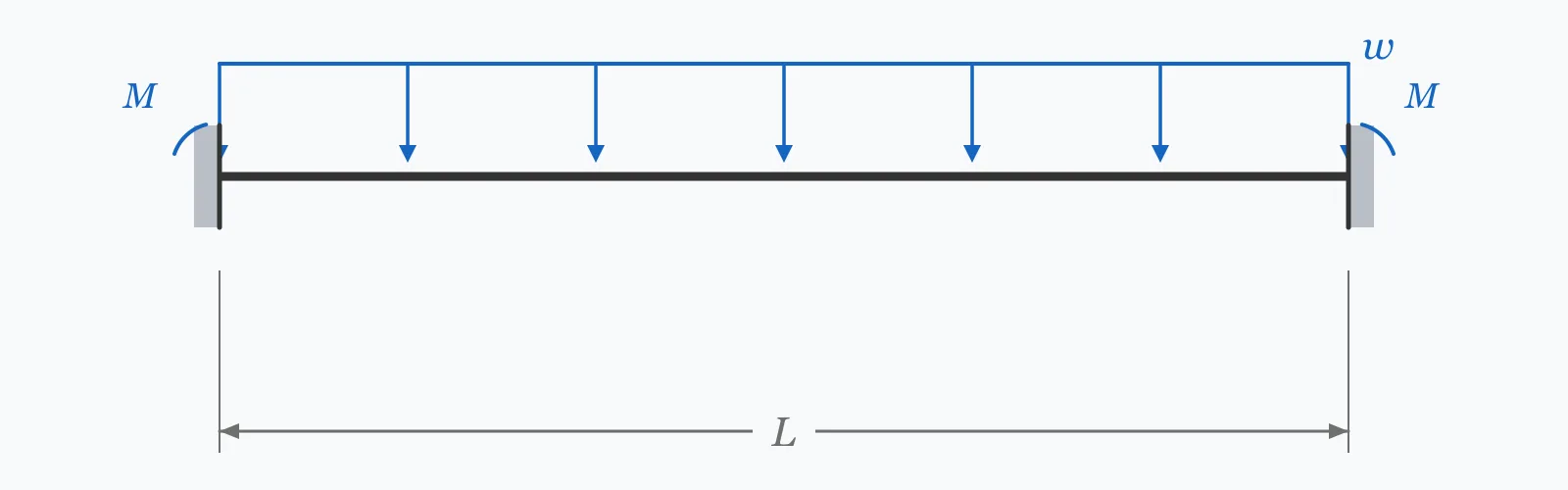
A beam built in at both ends develops moments at its supports even before any frame analysis begins. For a uniform load that moment is wL²/12; for a central point load it is PL/8. Enter the span and either or both loads to get each contribution and their sum — the starting values for moment distribution or any stiffness-based frame analysis.
Calculator
Units:
m
Clear span between the fixed supports
kN/m
Distributed load along the span; enter 0 if none
kN
Concentrated load at midspan; enter 0 if none
Calculation Result
Press Calculate for the fixed end moment from the uniform load, the contribution from the central point load, and their total. The moments act at both supports and are equal in magnitude but opposite in sense.
Step-by-Step Solution
Preliminary design aid. Results follow the published formulas cited
below and are intended for estimating, study and early design. Final design must be
verified by a licensed Professional Engineer against the code in force for your project.
Key Benefits
✓Handles uniform load, central point load, or both together by superposition
✓Returns each contribution separately, so their relative size is visible
✓Provides the starting values for moment distribution and stiffness analysis
✓Includes the full fixed end moment table for the standard load cases
✓Sensitivity chart shows the quadratic effect of span on the uniform-load term
✓Shareable links and CSV export for calculation records
What Is Fixed End Moment?
A fixed end moment is the moment that develops at the support of a beam whose ends are prevented from rotating. Because the supports resist rotation, they must apply a moment to the beam, and that moment exists purely as a consequence of the restraint. For a uniformly distributed load the value is wL²/12 at each end; for a concentrated load at midspan it is PL/8. Both act to bend the beam in the opposite sense to the midspan moment, which is why they reduce it.
Why continuity is worth having
A simply supported beam under uniform load carries wL²/8 at midspan and nothing at the supports. Fix both ends and the picture changes: wL²/12 appears at each support and the midspan moment falls to wL²/24, a third of the simply supported value. The peak moment anywhere in the beam drops from wL²/8 to wL²/12, a 33% reduction — achieved purely by restraining rotation, with no extra material. This is the fundamental economic argument for continuous and rigid-jointed construction.
The starting point for moment distribution
Real frames are neither fully fixed nor fully pinned; joints rotate by an amount that depends on the relative stiffness of everything meeting there. Moment distribution handles this by first assuming full fixity, computing the fixed end moments, then releasing each joint and sharing the out-of-balance moment among the members in proportion to their stiffness, carrying over half of each correction to the far end. Every cycle of that process starts from the numbers this calculator produces.
Formula
FEM = wL² / 12
Fixed end moment at each support of a built-in beam under uniform load
Related Formulas
FEM = PL / 8
FEM_A = Pab² / L², FEM_B = Pa²b / L²
M_midspan = wL²/24
FEM = wL² / 8
Variable Definitions
Symbol
Variable
Unit
Description
FEM
Fixed End Moment
kN·m
Moment developed at a support where rotation is fully prevented.
w
Uniform Load
kN/m
Distributed load along the full span. Contributes wL²/12 at each end.
P
Central Point Load
kN
Concentrated load at midspan. Contributes PL/8 at each end.
L
Span
m
Distance between supports. The uniform-load term grows with its square, the point-load term linearly.
M_total
Total Fixed End Moment
kN·m
Sum of the individual contributions, valid because the beam remains linear and elastic.
How to Use This Calculator
Confirm the end conditions are genuinely fixedFull fixity requires the support to prevent rotation completely. A beam framing into a stiff column or cast monolithically with a wall approaches it; a bolted end plate provides only partial restraint, and the real moment falls between the fixed and simply supported values.
Enter the span between support facesUse the clear span between the points of restraint. The uniform-load term varies with the square of span, so a 5% error becomes a 10% error in the moment.
Enter each load type separatelyLeave either field at zero if that load does not apply. The calculator computes each contribution independently and adds them, which is valid while the beam stays linear and elastic.
Note the sense of the momentsFixed end moments at the two supports are equal in magnitude and opposite in sense for a symmetric load, both acting to hog the beam over the supports. The tension face is therefore the top of the beam at the supports and the bottom at midspan.
Carry the values into the frame analysisFor a continuous beam or frame, these are the starting values for moment distribution. Lock the joints, apply these moments, then release each joint in turn and distribute the imbalance by relative stiffness.
Worked Examples
Example 1
A beam of 6.0 m span is fully fixed at both ends and carries a uniformly distributed load of 10 kN/m. Find the fixed end moments and compare against the simply supported case.
Step-by-Step Solution
Fixed end moment from the uniform load: FEM = wL²/12 = 10 × 6.0² / 12
= 10 × 36 / 12 = 360 / 12 = 30.00 kN·m at each support
No point load is applied, so the point-load contribution is 0.00 kN·m
Total fixed end moment: 30.00 kN·m at each end
Midspan moment of the fixed beam: wL²/24 = 360/24 = 15.00 kN·m
Compare with a simply supported beam: wL²/8 = 360/8 = 45.00 kN·m at midspan
The peak moment anywhere in the fixed beam is 30.00 kN·m against 45.00 kN·m simply supported — a 33% reduction achieved entirely by restraining the ends.
Example 2
The same 6.0 m fixed beam, now carrying both the 10 kN/m uniform load and a 40 kN point load at midspan. Superposition combines the two independent solutions.
Note the asymmetry between load types: for the uniform load the support moment is twice the midspan moment, while for the point load the two are equal in magnitude.
Design consequence: as point loads become a larger fraction of the total, the advantage of end fixity diminishes, because the point-load case redistributes less favourably than the uniform one.
Span Sensitivity
The uniform-load term grows with the square of span while the point-load term grows linearly, so their relative importance shifts as the beam lengthens. Switch between the curves to compare. The marker shows your current span.
Total FEM vs Beam Length (L)
Recomputed live from your inputs. The marker shows your current value.
Line chart of Total FEM against Beam Length (L). The same
values are listed in the data table below.
Values plotted above, sampled across the beam length (l) range.
How to Interpret Your Results
Fixed end moments are analysis inputs rather than pass-or-fail results, so there is no code limit against which to check them. What matters is the relative size of the two contributions, and what the total implies for the member and its connections.
Total FEM: < 25Light support moments
A total fixed end moment of your result kN·m is modest, in the range of secondary beams and light framing. Confirm that the connection can genuinely develop this moment — a nominally fixed joint that cannot will shed the moment back to midspan.
Total FEM: 25 – 200Typical building frame range
A total fixed end moment of your result kN·m is normal for beams in building frames. These are the starting values for moment distribution; the final support moments after joint release will be lower wherever the adjoining members are less than infinitely stiff.
Total FEM: ≥ 200Heavy moments — the connection will govern
A total fixed end moment of your result kN·m is substantial, and developing it requires a full-strength moment connection. At this level the joint detail is usually more expensive than the beam, and a simply supported arrangement with a deeper section may cost less overall.
FEM (Point): ≥ 0.001Point load contributing to the support moment
The central point load adds your result kN·m at each support. Unlike the uniform-load term, this contribution grows only linearly with span, so its relative importance falls as the beam gets longer.
Common Mistakes to Avoid
Assuming a bolted connection provides full fixity
Why it matters:Full fixity requires zero rotation. A bolted end plate or a cleated connection rotates under load, so the real support moment falls short of the fixed value and the midspan moment rises correspondingly.
✓How to avoid it:Classify the connection as rigid, semi-rigid or nominally pinned per the relevant code. Only genuinely rigid connections develop the full fixed end moment; semi-rigid joints need a rotational stiffness in the analysis.
Using wL²/12 for a propped cantilever
Why it matters:A beam fixed at one end and pinned at the other is a different problem. Its support moment is wL²/8, not wL²/12 — 50% higher — because there is no opposing restraint at the far end to share the moment.
✓How to avoid it:Match the formula to the actual end conditions. The FEM table below lists the standard cases; getting the support arrangement right matters more than precision in the load.
Forgetting that fixed end moments hog the beam
Why it matters:Support moments put the top face of the beam in tension, the opposite of midspan. In reinforced concrete this determines where the top steel goes, and getting it wrong is a serious detailing error.
✓How to avoid it:Sketch the bending moment diagram before detailing. Top reinforcement over supports, bottom reinforcement at midspan, with the change occurring at the points of contraflexure.
Treating fixed end moments as final design moments
Why it matters:In a real frame, joints rotate and moments redistribute. The fixed end moment is the first step of moment distribution, not its output — the final support moment is typically lower.
✓How to avoid it:Complete the moment distribution or run a stiffness analysis. Use fixed end moments as final values only where the supports genuinely provide full rotational restraint.
Ignoring the sign convention when combining spans
Why it matters:In moment distribution, the sense of each moment matters. Adding magnitudes without regard to sign produces an out-of-balance value at the joint that is entirely wrong.
✓How to avoid it:Adopt one convention — clockwise-positive is common — and apply it consistently at every joint. Most moment distribution errors are sign errors.
Overlooking support settlement
Why it matters:A fixed-ended beam is sensitive to relative support movement in a way a simply supported one is not. Differential settlement of just a few millimetres induces substantial additional moments in a stiff member.
✓How to avoid it:Where settlement is possible, include the induced moment 6EIΔ/L² in the analysis, or reconsider whether full fixity is desirable on compressible ground.
Practical Applications
▸Starting values for moment distribution in continuous beams and frames
▸Preliminary design of fixed-ended and continuous beams
▸Estimating support moments for reinforcement detailing in concrete
▸Sizing moment connections in steel frames
▸Assessing the benefit of continuity against simply supported framing
▸Checking induced moments from support settlement in stiff members
Industry Use Cases
Reinforced concrete design
Continuous slabs and beams are cast monolithically and behave as fixed at internal supports. Fixed end moments set where top reinforcement is required and how far it must extend past the support, which is the detail most often queried on site.
Steel frame design
Whether to use moment connections is a cost decision. Fixity cuts the beam moment by a third, but the connection to develop it can cost more than the steel saved — so engineers compare the two schemes explicitly at the outset.
Structural education and checking
Moment distribution remains the fastest way to sanity-check a computer frame analysis by hand. Starting from fixed end moments and running two or three cycles gets close enough to confirm that a model is behaving sensibly.
Expert Tips
💡End fixity cuts the peak moment by a third under uniform load — the strongest argument for continuous construction.
💡The uniform-load term grows with span squared while the point-load term grows linearly; on long spans the distributed load dominates.
💡PL/8 equals wL²/12 when P = 2wL/3 — a quick way to judge which load type is driving the support moment.
💡A propped cantilever gives wL²/8, half again more than a fully fixed beam. Check the end conditions before picking a formula.
💡Superposition is valid while the beam is elastic, so combine load cases by simple addition.
💡Fixed-ended beams are sensitive to support settlement; on compressible ground the induced moments can exceed the applied ones.
Advantages & Limitations
Advantages
✓Exact closed-form results for the standard load cases
✓Handles combined loading by straightforward superposition
✓Provides the starting values every moment distribution needs
✓Quantifies the benefit of continuity directly and immediately
✓Simple enough to check by hand during a design review
Limitations
!Assumes fully fixed supports; real connections are usually semi-rigid and develop less
!Covers uniform load and central point load only — off-centre and partial loads need the general expressions
!Assumes a prismatic beam of constant section along the span
!Takes no account of support settlement, which induces substantial additional moments
!Gives the first step of moment distribution, not the final redistributed moments
!Ignores axial force interaction, which matters in beam-columns
!Assumes linear elastic behaviour, so no plastic redistribution is included
Fixed End Moments by Load and Support Case
The standard cases used to start any moment distribution. Note how the support arrangement changes the coefficient as much as the load type does — a propped cantilever carries half again the moment of a fully fixed beam under the same uniform load.
Standard fixed end moments for prismatic beams. Moments at the supports hog the beam; midspan moments sag.
The moment that develops at the support of a beam whose ends are prevented from rotating. For a uniformly loaded beam fixed at both ends it is wL²/12 at each support; for a central point load it is PL/8.
Why is the fixed end moment wL²/12?
It follows from requiring zero rotation at both ends. Superposing the simply supported rotation from the load with the rotation from an applied end moment, and setting the sum to zero, gives wL²/12 as the moment needed to hold the end straight.
How much does end fixity reduce the moment?
By a third under uniform load. A simply supported beam peaks at wL²/8 at midspan; a fixed-ended one peaks at wL²/12 at the supports, with only wL²/24 at midspan. That 33% reduction is achieved without any extra material.
What is the fixed end moment for a point load?
PL/8 at each end for a load at midspan. For a load at distance a from end A and b from end B, the moments are unequal: Pab²/L² at A and Pa²b/L² at B, with the larger value at the end nearer the load.
What is the moment distribution method?
An iterative hand method for indeterminate frames developed by Hardy Cross. Every joint is first locked and the fixed end moments computed; joints are then released in turn, the out-of-balance moment shared by relative stiffness, and half of each correction carried over to the far end.
Do bolted connections provide full fixity?
Rarely. Most bolted connections are semi-rigid, rotating under load and developing only part of the fixed end moment. Full fixity requires a rigid connection detailed to transmit the moment — usually a fully welded joint or a substantial extended end plate.
Where is the maximum moment in a fixed-ended beam?
At the supports. Under uniform load the support moment is wL²/12 and the midspan moment only wL²/24, so the supports carry twice as much. This is why continuous concrete beams need their heaviest reinforcement over the supports.
Can I add fixed end moments from different loads?
Yes, provided the beam remains linear and elastic, which is the normal service condition. Superposition lets you compute each load case independently and sum the results, and it keeps each contribution visible for checking.
What is a propped cantilever?
A beam fixed at one end and simply supported at the other. Its support moment under uniform load is wL²/8, half again more than a fully fixed beam, because there is no restraint at the far end to share the moment.
How does support settlement affect a fixed beam?
Significantly. A relative settlement Δ between the two ends induces a moment of 6EIΔ/L² in addition to the load moments. Stiff beams on compressible ground can develop settlement moments larger than the applied ones, which is a real argument against full fixity in some conditions.
Glossary
Fixed end moment
The moment developed at a support that fully prevents rotation of the beam end.
Built-in beam
A beam rigidly restrained against rotation at both supports, also called encastré or fixed-ended.
Propped cantilever
A beam fixed at one end and simply supported at the other, an indeterminate case with one redundancy.
Moment distribution
Hardy Cross's iterative method for indeterminate frames, starting from fixed end moments and releasing joints in turn.
Carry-over factor
The proportion of a moment applied at one end that appears at the far end, equal to 0.5 for a prismatic member fixed at that end.
Distribution factor
The share of an out-of-balance joint moment taken by each member, in proportion to its relative stiffness.
Hogging moment
A moment that puts the top face of a beam in tension, as occurs over supports in continuous construction.
Point of contraflexure
The location where bending moment passes through zero and the tension face changes from top to bottom.
Semi-rigid connection
A joint with partial rotational stiffness, developing some but not all of the fixed end moment.
Scientific & Standards References
Cross, H., Analysis of Continuous Frames by Distributing Fixed-End Moments, Transactions ASCE Vol. 96 (1932) — American Society of Civil Engineers
Hibbeler, R. C., Structural Analysis, 10th Edition — Chapter 12: Displacement Method of Analysis: Moment Distribution — Pearson
AISC Steel Construction Manual, 16th Edition — Beam Diagrams and Formulas (Part 3) — American Institute of Steel Construction
Roark's Formulas for Stress and Strain, 9th Edition — Table 8.1: Reaction and Deflection Formulas for Straight Beams — McGraw-Hill
EN 1992-1-1 §5.5 — Linear elastic analysis with limited redistribution — CEN
Conclusion
Fixed end moments are wL²/12 for a uniform load and PL/8 for a central point load, developing at each support of a beam whose ends cannot rotate. They matter for two reasons. As design values, they quantify the benefit of continuity: end fixity cuts the peak moment by a third under uniform load, without adding material. As analysis inputs, they are the first step of moment distribution and of every stiffness-based frame analysis. The assumption to check hardest is the one they rest on — real connections are usually semi-rigid, developing less than the full moment, and a beam analysed as fixed but built as semi-rigid will carry more at midspan than the calculation shows.
Enter your own beam above, then sweep the span in the chart to see how the uniform and point load contributions diverge.