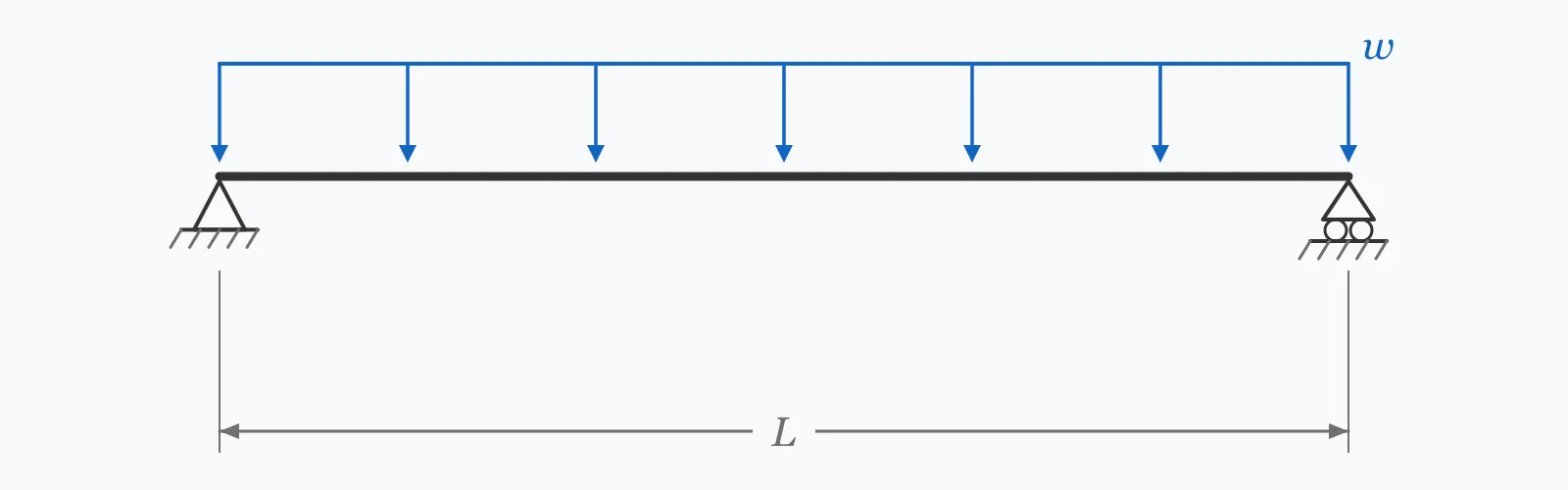
A compact steel beam reaches its plastic moment, Mn = Fy·Zx, and AISC LRFD applies a resistance factor of 0.90 to give the design capacity ϕMn. Enter the yield strength, plastic section modulus and applied factored moment, and this calculator returns the capacity, the demand/capacity ratio, and the Zx you would need for the section to work.
From section tables — the plastic value Zx, not the elastic Sx
kN·m
Factored moment from the governing LRFD combination
Calculation Result
Press Calculate for the nominal moment Mn, the design capacity ϕMn, the demand/capacity ratio and the required Zx. A D/C ratio at or below 1.0 means the section passes the flexural check.
Step-by-Step Solution
Preliminary design aid. Results follow the published formulas cited
below and are intended for estimating, study and early design. Final design must be
verified by a licensed Professional Engineer against the code in force for your project.
Key Benefits
✓Applies the AISC LRFD flexural check exactly as written, with ϕ = 0.90
✓Reports the demand/capacity ratio, the number reviewers actually look for
✓Returns the required Zx so section selection becomes a table lookup
✓Warns when the ratio sits above 0.95, where reserve capacity is minimal
✓Sensitivity chart shows how the D/C ratio tracks the applied moment
✓Exports a CSV calculation record and shares as a reproducible link
What Is Steel Beam Design?
Flexural design of a steel beam compares the moment the structure demands against the moment the section can supply. For a compact, adequately braced section the supply is the plastic moment Mn = Fy·Zx, reached when every fibre across the depth has yielded. AISC 360 §F2.1 gives exactly this expression, and the LRFD resistance factor for flexure, ϕb = 0.90, converts it into a design capacity ϕMn that is compared against the factored moment Mu from the governing load combination.
Reading the demand/capacity ratio
Dividing demand by capacity gives a dimensionless utilisation. A ratio of 1.0 means the beam is exactly at its design limit, 0.75 means a quarter of the capacity is unused, and anything above 1.0 fails. Practitioners generally aim between 0.85 and 0.95 for efficiency: much lower wastes steel, much higher leaves nothing for the load changes that arrive during construction. The ratio is also what a checking engineer scans first across a whole beam schedule.
What this check does not cover
Reaching Mn requires two conditions this calculation assumes rather than verifies. The section must be compact, meaning its flange and web slenderness fall within AISC Table B4.1b so that local buckling does not intervene. And the compression flange must be braced closely enough that lateral-torsional buckling does not govern — beyond the limiting length Lp, capacity falls below Mp regardless of the section's own strength. Shear, deflection, vibration and web crippling are all separate checks.
Formula
ϕM_n = 0.90 · F_y · Z_x
Design flexural strength of a compact, adequately braced steel section under AISC LRFD
The plastic moment of the section, before any resistance factor is applied.
ϕM_n
Design Moment Capacity
kN·m
Nominal capacity multiplied by ϕb = 0.90, the value compared against the factored moment.
F_y
Yield Strength
MPa
Specified minimum yield strength. 345 MPa for ASTM A992, 355 MPa for S355.
Z_x
Plastic Section Modulus
×10³ mm³
Section property from the tables, about the axis of bending. Do not substitute the elastic modulus S.
M_u
Applied Factored Moment
kN·m
Maximum moment from the governing LRFD load combination, such as 1.2D + 1.6L.
D/C
Demand/Capacity Ratio
—
Utilisation of the section. At or below 1.0 passes; above 1.0 fails.
How to Use This Calculator
Use the factored moment, not the service momentLRFD compares factored demand against factored capacity. Take Mu from the governing combination, typically 1.2D + 1.6L for gravity loading. Using service loads here would overstate the available margin by roughly 40%.
Take Zx from the tables, about the correct axisUse the plastic modulus Zx for strong-axis bending, or Zy for weak-axis. Substituting the elastic modulus Sx understates capacity by 12 to 18% for a wide-flange section.
Enter the specified yield strengthUse the specified minimum, not a mill certificate value. ASTM A992 is 345 MPa (50 ksi); European S355 is 355 MPa. Actual yield is typically higher, and that margin is part of the code's reliability basis rather than yours to spend.
Read the demand/capacity ratioAt or below 1.0 the section passes the flexural check. Between 0.85 and 0.95 is efficient practice. Above 1.0, use the returned required Zx to find a larger section directly in the tables.
Then verify what this check assumesConfirm the section is compact, that the unbraced length is within Lp, and separately check shear, deflection and — for long floor spans — vibration. Passing the moment check alone does not make a beam adequate.
Worked Examples
Example 1
A floor beam in ASTM A992 steel (Fy = 345 MPa) has a plastic section modulus Zx = 629 ×10³ mm³. The governing load combination produces a factored moment of 150 kN·m. Check the flexural capacity.
Check: D/C = 0.768 ≤ 1.0, so the section passes with about 23% reserve. The required Zx of 483 ×10³ mm³ is well below the 629 ×10³ mm³ provided, confirming a lighter section could be considered if deflection allows.
Example 2
The same beam, but the floor is reassigned to storage and the factored moment rises to 210 kN·m. This is the case where the check fails and the required modulus becomes the design tool.
Select from tables the lightest section with Zx ≥ 676 ×10³ mm³
Alternative: keeping the section and raising the grade to S460 gives ϕMn = 0.90 × 460 × 629,000 / 10⁶ = 260.4 kN·m, so D/C falls to 0.806 and the section works.
Note the contrast with deflection: a higher grade fixes a strength failure but does nothing at all for a stiffness failure, because deflection depends on E, which is the same for every grade.
Demand Sensitivity
Capacity is fixed by the section, so the demand/capacity ratio rises linearly with applied moment. Sweep the moment to find where your section crosses D/C = 1.0 — that intersection is the largest moment it can carry. The marker shows your current demand.
Demand/Capacity Ratio vs Applied Moment (Mu)
Recomputed live from your inputs. The marker shows your current value.
Line chart of Demand/Capacity Ratio against Applied Moment (Mu). The same
values are listed in the data table below.
Values plotted above, sampled across the applied moment (mu) range.
How to Interpret Your Results
The demand/capacity ratio is the single number this check produces. It is dimensionless, directly comparable across every beam in a schedule, and the value a checking engineer scans for first.
Demand/Capacity Ratio: < 0.5Substantially oversized for bending
A demand/capacity ratio of your result means less than half the flexural capacity is used. Either a lighter section would work, or the beam is being governed by something else — deflection, vibration or a stability requirement. Confirm which before downsizing.
Demand/Capacity Ratio: 0.5 – 0.95Adequate with sensible reserve
A demand/capacity ratio of your result passes the flexural check with useful margin. This is the range most efficient designs land in — enough reserve to absorb load changes during construction without wasting steel.
Demand/Capacity Ratio: 0.95 – 1Passes, but with almost no reserve
A demand/capacity ratio of your result is within limits but leaves under 5% spare. Any increase in load, any change of section during procurement, or any error in the load take-off pushes this beam over. Consider the next size up.
Demand/Capacity Ratio: 1 – 1.25Inadequate — section must change
A demand/capacity ratio of your result exceeds 1.0, so the section fails its flexural check. Use the required Zx returned above to select a larger section, add an intermediate support, or specify a higher-grade steel.
A demand/capacity ratio of your result indicates the section is far short of what is required. A change of serial size alone is unlikely to close this gap — revisit the framing arrangement, span or load path rather than simply upsizing.
Common Mistakes to Avoid
Entering the elastic section modulus Sx instead of the plastic Zx
Why it matters:The AISC plastic moment expression requires Zx. For a wide-flange section Zx exceeds Sx by 12 to 18%, so using Sx understates capacity and leads to an unnecessarily heavy beam.
✓How to avoid it:Read Zx from the section tables. If your table gives only Sx and the section is compact, Zx is roughly 1.14·Sx for a typical rolled shape — but look it up rather than scaling.
Using service loads instead of factored loads
Why it matters:LRFD pairs factored demand with a ϕ-reduced capacity. Comparing an unfactored moment against ϕMn overstates the margin by around 40% and can pass a beam that genuinely fails.
✓How to avoid it:Use Mu from the governing factored combination. Service loads belong in the deflection check, not here.
Assuming Mn = Fy·Zx without checking the unbraced length
Why it matters:The plastic moment is only reachable if the compression flange is braced within Lp. Beyond that, lateral-torsional buckling reduces capacity — and beyond Lr the reduction is severe.
✓How to avoid it:Compute Lb and compare it against Lp from the tables. If Lb exceeds Lp, use the AISC 360 §F2.2 reduced capacity with the appropriate Cb factor.
Applying the plastic moment to a non-compact section
Why it matters:A slender flange or web buckles locally before the section can plastify, so the plastic moment is never developed and the calculated capacity is unconservative.
✓How to avoid it:Check flange and web slenderness against AISC Table B4.1b. Non-compact and slender sections are designed on reduced capacity per §F3 or §F5.
Treating the moment check as the whole design
Why it matters:A beam that passes in bending can still fail in shear at a heavily loaded short span, deflect beyond L/360, or vibrate unacceptably on a long floor span.
✓How to avoid it:Run shear, deflection and — for spans beyond about 8 m — vibration as separate checks. On long spans, deflection governs the section choice far more often than bending does.
Using mill-certificate yield strength rather than the specified minimum
Why it matters:Actual yield strength routinely exceeds the specified minimum by 10 to 20%, but that overstrength is part of the code's reliability calibration and is also what makes capacity design work.
✓How to avoid it:Always use the specified minimum yield strength — 345 MPa for A992, 355 MPa for S355 — in design calculations.
Practical Applications
▸Sizing floor and roof beams in steel-framed buildings
▸Checking transfer beams and headers carrying concentrated loads
▸Verifying existing beams against increased loading in change-of-use assessments
▸Selecting sections quickly from the required plastic modulus
▸Comparing steel grades when a section is fixed by geometry
▸Checking crane runway and monorail beams for flexural adequacy
Industry Use Cases
Commercial building design
Engineers run this check across an entire beam schedule and sort by demand/capacity ratio. Beams below 0.6 are candidates for downsizing, and those above 0.95 get flagged for review before drawings are issued.
Structural assessment and retrofit
When a building changes use, the factored moment can rise sharply while the sections stay fixed. Computing the new D/C ratio across the existing frame identifies exactly which members need strengthening — usually a small fraction of the total.
Steel fabrication and value engineering
Fabricators propose alternative sections during procurement when a specified size is unavailable. Recomputing the required Zx confirms in seconds whether a substitution is acceptable, which keeps the programme moving.
Expert Tips
💡Aim for a D/C ratio between 0.85 and 0.95 — efficient without leaving the design brittle to load changes.
💡Compute the required Zx first, then enter the tables. It turns section selection into a lookup instead of a trial-and-error loop.
💡On spans beyond about 8 m, check deflection before bending. It usually governs, and it will decide the section anyway.
💡A higher steel grade raises moment capacity proportionally but does nothing for deflection, since E is identical across grades.
💡Record the assumed unbraced length alongside the result — it is the assumption most likely to be challenged in review.
💡Where a beam fails by a small margin, adding a brace to reduce Lb is often cheaper than upsizing the whole member.
Advantages & Limitations
Advantages
✓Reduces the flexural check to a single, unambiguous comparison
✓Produces a dimensionless ratio directly comparable across an entire schedule
✓Returns the required section modulus, making section selection a table lookup
✓Matches AISC 360 §F2.1 exactly, so results are defensible in review
✓Fast enough to run across every member during scheme design
Limitations
!Assumes a compact section; slender flanges or webs require the reduced capacity of §F3 or §F5
!Assumes the compression flange is braced within Lp — no lateral-torsional buckling check is performed
!Covers flexure only, not shear, web crippling, deflection or vibration
!Applies the LRFD resistance factor; ASD users need the corresponding safety factor Ωb = 1.67
!Does not account for composite action with a concrete slab, which can substantially raise capacity
!Takes no account of holes, notches or net-section loss in the flanges
Design Capacity by Steel Grade
Capacity scales directly with yield strength while stiffness does not, so a higher grade helps a strength-governed beam and does nothing for a deflection-governed one. Values below use the same Zx = 629 ×10³ mm³ section.
Design flexural capacity ϕMn = 0.90·Fy·Zx for a compact, braced section with Zx = 629 ×10³ mm³. Deflection is unaffected by grade.
For a compact, adequately braced section, the nominal capacity is Mn = Fy·Zx. Under AISC LRFD the design capacity is ϕMn = 0.90·Fy·Zx, and this must be at least the factored moment Mu from the governing load combination.
What is a good demand/capacity ratio?
Between 0.85 and 0.95 is efficient practice. It uses most of the section while retaining reserve for load changes during construction. Below 0.6 usually means something other than bending governs; above 1.0 the section fails.
Why is the resistance factor 0.90?
ϕb = 0.90 is the flexural resistance factor calibrated by AISC to give a consistent reliability index against the LRFD load factors. It accounts for variability in material strength, section dimensions and the accuracy of the capacity model.
What is the difference between Zx and Sx?
Sx is the elastic section modulus, corresponding to first yield at the extreme fibre. Zx is the plastic modulus, corresponding to full yielding across the section. Zx is larger — by 12 to 18% for a rolled wide-flange shape — and is what LRFD flexural design uses.
How do I find the required section size?
Compute Zx,req = Mu/(ϕ·Fy), then choose the lightest section in the tables with a plastic modulus at or above that value. This turns section selection into a single lookup rather than iterative guessing.
What is a compact section?
One whose flange and web width-to-thickness ratios are low enough that the section can fully plastify before any element buckles locally. AISC Table B4.1b sets the limits. Most rolled wide-flange shapes in common grades are compact in flexure.
Does this check cover lateral-torsional buckling?
No. It assumes the compression flange is braced within Lp. If the unbraced length exceeds Lp, capacity drops below Mp and AISC 360 §F2.2 or §F2.3 applies, with the Cb factor accounting for the moment gradient along the unbraced segment.
Should I use LRFD or ASD?
Both are permitted by AISC 360 and give similar sections. LRFD compares Mu against ϕMn with ϕ = 0.90; ASD compares the service moment against Mn/Ωb with Ωb = 1.67. Use whichever the project specification requires, and do not mix them.
Will a higher steel grade solve a failed beam?
It will solve a strength failure, since capacity scales directly with Fy — moving from 345 to 460 MPa raises capacity by a third. It will not solve a deflection failure, because deflection depends on the modulus of elasticity, which is the same for every structural grade.
What else must I check after bending?
Shear at the supports, deflection against the serviceability limit, web local yielding and crippling under concentrated loads, and — for floor spans beyond roughly 8 m — vibration. On long spans, deflection normally governs the final section choice.
Glossary
Nominal moment (Mn)
The moment capacity of a section before any resistance factor is applied; equal to Fy·Zx for a compact braced member.
Design moment (ϕMn)
Nominal capacity reduced by the resistance factor ϕb = 0.90, compared directly against the factored moment.
Resistance factor (ϕ)
A strength-reduction factor calibrated to give consistent reliability, taken as 0.90 for flexure in AISC LRFD.
Demand/capacity ratio
Factored moment divided by design capacity; a dimensionless utilisation that must not exceed 1.0.
Plastic section modulus (Zx)
The section property corresponding to full yielding across the cross-section, used in plastic flexural design.
Compact section
A section whose element slenderness permits full plastification before local buckling occurs.
Lateral-torsional buckling
Buckling in which a beam's compression flange displaces sideways and the section twists, reducing capacity when bracing is widely spaced.
Unbraced length (Lb)
The distance between points of lateral restraint to the compression flange.
Limiting length Lp
The maximum unbraced length at which a compact section can still develop its full plastic moment.
Factored moment (Mu)
The maximum moment from the governing LRFD load combination, such as 1.2D + 1.6L.
Scientific & Standards References
AISC 360-22 §F2 — Doubly Symmetric Compact I-Shaped Members Bent About Their Major Axis — American Institute of Steel Construction
AISC 360-22 Table B4.1b — Width-to-Thickness Ratios for Compression Elements in Flexure — American Institute of Steel Construction
AISC Steel Construction Manual, 16th Edition — Part 3: Design of Flexural Members — American Institute of Steel Construction
ASCE/SEI 7-22 §2.3 — Combining Factored Loads Using Strength Design — American Society of Civil Engineers
EN 1993-1-1 §6.2.5 — Bending moment resistance of cross-sections — CEN
ASTM A992/A992M — Standard Specification for Structural Steel Shapes — ASTM International
Conclusion
The AISC LRFD flexural check reduces to comparing the factored moment against 0.90·Fy·Zx, and the demand/capacity ratio it produces is the number that carries across an entire beam schedule. Aim between 0.85 and 0.95: lower wastes steel, higher leaves nothing for the load changes that arrive later. The check's simplicity rests on two assumptions worth verifying explicitly — that the section is compact, and that the compression flange is braced within Lp — and on remembering that bending is only the first of several checks, with deflection frequently governing the final section on long spans.
Check your own section above, then sweep the applied moment in the chart to find exactly where it crosses D/C = 1.0.