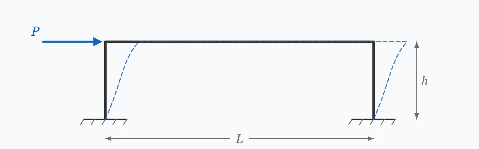
In a single-bay rigid frame, a lateral load splits equally between the two columns, giving V = P/2 each. The Portal Method then assumes an inflection point at mid-height, so the column moment is V·h/2. Enter the lateral load and column height for both. It is a hand approximation for preliminary sizing, not a substitute for frame analysis.
Calculator
Units:
kN
Horizontal force at beam level, from wind or seismic action
m
Base to beam centreline height
Calculation Result
Press Calculate for the shear carried by each column and the resulting column moment. The moment occurs at both the base and the beam connection, equal in magnitude and opposite in sense about the mid-height inflection point.
Step-by-Step Solution
Preliminary design aid. Results follow the published formulas cited
below and are intended for estimating, study and early design. Final design must be
verified by a licensed Professional Engineer against the code in force for your project.
Key Benefits
✓Gives column shear and moment from just two inputs, with no section properties needed
✓Fast enough for scheme design and for sanity-checking a computer model
✓States its two governing assumptions explicitly rather than hiding them
✓Includes the comparison against pinned-base and multi-bay cases
✓Sensitivity chart shows the linear relationship between height and moment
✓Shareable links and CSV export for calculation records
What Is Portal Frame Analysis?
A portal frame is a rigid frame of two columns and a beam, with moment-resisting connections at the corners. Under lateral load it is statically indeterminate: equilibrium alone gives three equations but the frame has more unknowns, so the analysis needs additional information about stiffness. The Portal Method supplies that information through assumptions instead, making the frame determinate and solvable by hand.
The two assumptions
First, the lateral shear divides equally between the columns — exact for a symmetric single-bay frame with identical columns, approximate otherwise. Second, each column has a point of contraflexure at mid-height, meaning the bending moment passes through zero there. That second assumption is what converts the problem into a determinate one: taking moments about the inflection point gives the column moment directly as V times half the height.
When the mid-height assumption holds
An inflection point at mid-height implies equal rotational restraint at the top and bottom of the column — which is what a fixed base and a stiff beam together provide. Where the base is pinned, there is no restraint below, the inflection point moves to the base itself, and the moment at the top becomes the full V·h rather than V·h/2. Where the beam is flexible relative to the columns, the inflection point drifts downward. The method is therefore best suited to fixed-base frames with beams at least as stiff as their columns.
Formula
V_col = P / 2
Shear in each column of a single-bay frame under lateral load P
Related Formulas
M = V_col · h / 2
M = V_col · h
V_interior = 2 · V_exterior
N = ± M_overturning / L
Variable Definitions
Symbol
Variable
Unit
Description
P
Lateral Load
kN
Horizontal force applied at beam level, typically from wind or seismic action.
V_col
Column Base Shear
kN
Horizontal shear carried by each column, half the applied load in a symmetric single-bay frame.
h
Column Height
m
Height from base to beam centreline. The moment grows linearly with it.
M
Maximum Column Moment
kN·m
Moment at the base and at the beam connection, equal to V·h/2 for a fixed-base frame.
L
Bay Width
m
Not entered here, but needed to find the column axial forces from the overturning couple.
How to Use This Calculator
Apply the lateral load at beam levelThe method assumes the load acts as a point force at the beam. For distributed wind pressure on a wall, first resolve it into an equivalent force at beam level, or analyse the column for the combined bending it produces.
Measure the height to the beam centrelineUse base to beam centreline rather than clear height. Since the moment grows linearly with height, the difference matters and the centreline is the correct reference for the frame model.
Confirm the bases are fixedThe mid-height inflection assumption relies on rotational restraint at the base. For a pinned base the inflection point drops to the base and the top moment doubles to V·h, so this calculator's result would be half the true value.
Find the column axial forces separatelyThe lateral load also produces an overturning couple, giving tension in one column and compression in the other of magnitude M_overturning/L. This calculator does not compute it, but it must be included in the column design.
Use it as a check, not as a final designPortal Method results are approximate. Use them for scheme design, for member selection ahead of analysis, and for sanity-checking a computer model, then confirm with a proper stiffness analysis for the final design.
Worked Examples
Example 1
A single-bay portal frame has 4.0 m tall columns with fixed bases and carries a lateral load of 50 kN at beam level. Find the column shear and moment.
Step-by-Step Solution
Lateral load divides equally between the two columns
Column base shear: V = P/2 = 50 / 2 = 25.00 kN in each column
The Portal Method places an inflection point at mid-height: 4.0 / 2 = 2.0 m above the base
Taking moments about that inflection point: M = V × h/2 = 25.00 × 2.0
M = 50.00 kN·m
This moment occurs at both the base and the beam connection, equal in magnitude and opposite in sense
Separately, the overturning couple produces axial force in the columns. For a 6 m bay: N = (50 × 4.0) / (2 × 6.0) = 16.67 kN, tension in the windward column and compression in the leeward.
Example 2
The same frame and load, but with pinned bases instead of fixed. This is the case where applying this calculator's result unchanged would halve the real moment.
Step-by-Step Solution
Column shear is unaffected by base fixity: V = P/2 = 25.00 kN, since it follows from horizontal equilibrium alone
With a pinned base the column carries no moment there, so the inflection point sits at the base rather than mid-height
Taking moments about the base: M_top = V × h = 25.00 × 4.0 = 100.00 kN·m at the beam connection
Comparison: 100.00 kN·m against the 50.00 kN·m this calculator returns for a fixed base — exactly double
The frame is also far more flexible. Sway deflection for a pinned-base portal is roughly four times that of a fixed-base one under the same load.
Design consequence: base fixity halves the column moment but demands a moment-resisting foundation, which on poor ground can cost more than the steel it saves. The choice is a whole-system decision, not a member one.
Height Sensitivity
Column shear is set entirely by the applied load and does not change with height, so its curve is flat. The moment grows linearly with height, which is why tall single-storey frames are governed by their column moments rather than by shear. The marker shows your current height.
Max Column Moment vs Column Height (h)
Recomputed live from your inputs. The marker shows your current value.
Line chart of Max Column Moment against Column Height (h). The same
values are listed in the data table below.
Values plotted above, sampled across the column height (h) range.
How to Interpret Your Results
These are analysis quantities rather than pass-or-fail checks. What is worth reading is the relative size of shear and moment, which tells you whether the column will be governed by bending or by its connections.
Max Column Moment: < 30Light frame moments
A column moment of your result kN·m is modest, typical of a low single-storey frame under light lateral load. Confirm the base detail can develop it — a nominally fixed base that cannot will double the moment at the beam connection.
Max Column Moment: 30 – 250Typical portal frame range
A column moment of your result kN·m is normal for single-storey industrial and commercial frames. Size the column for combined axial force and bending, and detail the base and eaves connections to develop this moment.
Max Column Moment: ≥ 250Heavy moments — check the connections and the base
A column moment of your result kN·m is substantial. At this level the eaves connection and the moment-resisting foundation usually cost more than the frame members. Bracing the frame instead, where architecture allows, is often considerably cheaper.
Column Base Shear: ≥ 150High lateral load
A column shear of your result kN indicates a heavily loaded frame. Verify that the Portal Method is still appropriate — at this level, a proper stiffness analysis including second-order effects is warranted before member sizes are fixed.
Common Mistakes to Avoid
Applying the mid-height inflection assumption to a pinned-base frame
Why it matters:A pinned base carries no moment, so the inflection point sits at the base rather than mid-height. The moment at the beam connection is then V·h, exactly twice what this calculator returns.
✓How to avoid it:Confirm the base condition first. For pinned bases, use M = V·h at the top and zero at the base, and expect roughly four times the sway deflection.
Forgetting the column axial forces
Why it matters:Lateral load produces an overturning couple as well as shear, putting one column into tension and the other into compression. Sizing a column for bending alone ignores an interaction that frequently governs.
✓How to avoid it:Compute the axial force as the overturning moment divided by the bay width, then check the column under combined axial force and bending using the relevant interaction equation.
Using the Portal Method on a frame with flexible beams
Why it matters:The method assumes the beam is stiff enough to hold the column tops against rotation. Where the beam is significantly less stiff than the columns, the inflection point drifts well below mid-height and the moments redistribute.
✓How to avoid it:Check the relative stiffness of beam and columns. Where the beam is the more flexible member, use the Cantilever Method or a proper stiffness analysis instead.
Treating an approximate result as a final design value
Why it matters:The Portal Method replaces the compatibility equations of an indeterminate structure with two assumptions. It is close for regular frames but can be some way off for irregular ones, and it has no error bound.
✓How to avoid it:Use it for scheme design and for checking a model, then confirm the final design with a stiffness analysis that includes real member properties.
Ignoring second-order sway effects
Why it matters:Under lateral load the frame displaces, and the gravity load then acts through that displacement to add moment. For slender or heavily loaded frames this P-delta effect can add 10 to 20% to the column moments.
✓How to avoid it:Check the frame's elastic critical load factor. Where it falls below the code threshold — commonly 10 for elastic analysis — a second-order analysis or an amplification factor is required.
Distributing shear equally in a multi-bay frame
Why it matters:The Portal Method gives interior columns twice the shear of exterior ones, because each interior column serves two bays. Splitting equally across all columns understates the interior columns substantially.
✓How to avoid it:Assign shear in proportion to the number of bays each column serves: exterior columns take one share, interior columns two.
Practical Applications
▸Preliminary sizing of single-storey portal frames under wind load
▸Estimating column moments before running a frame analysis
▸Sanity-checking the output of a computer frame model
▸Comparing fixed-base and pinned-base schemes at concept stage
▸Sizing eaves and base connections for moment capacity
▸Teaching and examining indeterminate frame behaviour
Industry Use Cases
Industrial building design
Single-storey portal frames are the default for warehouses and factories. Engineers use the Portal Method at concept stage to size columns and judge whether moment-resisting bases are worth their foundation cost, before committing to a full analysis.
Structural checking and peer review
Reviewers use hand methods to validate computer output. A Portal Method calculation taking two minutes will catch a model with wrong support conditions or a misapplied load far faster than reading the input file.
Structural education
The Portal Method remains the standard introduction to approximate analysis, because it makes the role of assumptions in indeterminate structures explicit: two stated assumptions convert an unsolvable problem into a solvable one.
Expert Tips
💡Column shear depends only on the applied load, not on height — only the moment grows as the frame gets taller.
💡Fixed bases halve the column moment against pinned, but demand a moment-resisting foundation that can cost more than it saves.
💡Always compute the column axial forces from the overturning couple; bending alone is never the full check.
💡In a multi-bay frame, interior columns take twice the shear of exterior ones under this method.
💡Where architecture permits bracing, a braced frame is almost always cheaper than a moment frame of the same capacity.
💡Use the method to check a computer model — a two-minute hand calculation catches wrong supports faster than reading input files.
Advantages & Limitations
Advantages
✓Requires only two inputs and no section properties at all
✓Fast enough to use during concept design and in review meetings
✓Makes the role of assumptions in indeterminate analysis explicit
✓Extends naturally to multi-storey and multi-bay frames
✓Accurate enough for regular frames with fixed bases and stiff beams
Limitations
!Assumes fixed bases; a pinned-base frame carries twice the moment at the beam connection
!Assumes an inflection point exactly at mid-height, which requires balanced restraint above and below
!Assumes the beam is stiff relative to the columns
!Covers a symmetric single-bay frame; irregular geometry needs a full analysis
!Does not compute column axial forces from the overturning couple
!Ignores second-order sway effects, which add 10 to 20% for slender frames
!Takes no account of gravity loads acting simultaneously with the lateral load
Column Moment by Base Condition and Frame Type
The same 50 kN lateral load on 4 m columns. Base fixity is the single largest factor — it halves the peak moment and quarters the sway, at the cost of a moment-resisting foundation.
Portal Method results for a 50 kN lateral load on 4 m columns. Sway ratios are indicative and depend on relative member stiffness.
An approximate hand method for analysing rigid frames under lateral load. It makes a frame determinate through two assumptions: shear divides equally between columns in a bay, and every column has an inflection point at mid-height.
How do I calculate portal frame column moment?
Find the column shear as the lateral load divided by the number of columns, then multiply by half the column height: M = V·h/2. For a 50 kN load on 4 m columns, each column takes 25 kN shear and 50 kN·m moment.
Why is the inflection point assumed at mid-height?
Because a column with equal rotational restraint at both ends bends into an S-shape with zero moment at its middle. Fixed bases and a stiff beam produce that condition. Where the restraints differ, the inflection point moves towards the less restrained end.
What changes if the bases are pinned?
The moment at the base becomes zero and the inflection point moves there, so the moment at the beam connection doubles to V·h. Sway deflection also rises to roughly four times the fixed-base value under the same load.
How accurate is the Portal Method?
Within about 10 to 15% for regular frames with fixed bases and beams at least as stiff as the columns. Accuracy falls with irregular geometry, flexible beams and significant vertical load, and the method provides no error bound of its own.
How does shear distribute in a multi-bay frame?
Interior columns take twice the shear of exterior ones, because each interior column serves two bays while an exterior column serves one. For a two-bay frame the shares are 1:2:1 across the three columns.
Do I need to check axial force in the columns?
Yes. The lateral load produces an overturning couple that puts one column in tension and the other in compression, of magnitude equal to the overturning moment divided by the bay width. Combined axial force and bending frequently governs the column.
What is the difference between the Portal and Cantilever Methods?
Both assume mid-height inflection points, but they distribute shear differently. The Portal Method assigns shear by bay count and suits low, wide frames. The Cantilever Method assumes axial stress varies linearly across the frame like a cantilever beam, and suits tall, narrow frames.
Should I use a moment frame or a braced frame?
Braced frames are stiffer and cheaper for the same lateral capacity, so they win wherever the architecture tolerates diagonal members. Moment frames exist because open bays are often worth their cost premium — the decision is architectural as much as structural.
When do second-order effects matter?
When the frame is slender or heavily loaded in gravity. Sway lets the vertical load act through the horizontal displacement, adding moment. Codes set a threshold on the elastic critical load factor — commonly 10 — below which a second-order analysis or an amplification factor is required.
Glossary
Portal frame
A rigid frame of two columns and a beam with moment-resisting corner connections.
Portal Method
An approximate analysis assuming equal shear per bay and mid-height inflection points in every column.
Point of inflection
A location along a member where the bending moment passes through zero and curvature reverses.
Base shear
The horizontal force transmitted from a column into its foundation.
Sway
Lateral displacement of a frame under horizontal load, resisted by frame stiffness or by bracing.
Statically indeterminate
A structure whose reactions and internal forces cannot be found from equilibrium alone.
Overturning couple
The pair of axial forces induced in the columns by a lateral load acting at height.
Cantilever Method
An approximate frame analysis assuming axial stress varies linearly across the frame, suited to tall narrow frames.
Second-order effect
Additional moment arising when gravity load acts through the lateral displacement of a swaying frame.
Scientific & Standards References
Hibbeler, R. C., Structural Analysis, 10th Edition — Chapter 7: Approximate Analysis of Statically Indeterminate Structures — Pearson
AISC 360-22 Chapter C — Design for Stability — American Institute of Steel Construction
AISC Design Guide 1: Base Plate and Anchor Rod Design, 2nd Edition — American Institute of Steel Construction
EN 1993-1-1 §5.2 — Structural analysis: effects of deformed geometry — CEN
SCI P399 — Design of Steel Portal Frame Buildings to Eurocode 3 — Steel Construction Institute
Conclusion
The Portal Method turns an indeterminate frame into a solvable one with two assumptions: shear splits equally between the columns, and each column has an inflection point at mid-height. That gives V = P/2 and M = V·h/2, enough to size columns at concept stage or to check a computer model in two minutes. Both assumptions deserve verification before the result is trusted — a pinned base doubles the moment at the beam connection, and a beam more flexible than its columns moves the inflection point downward. And the method answers only half the question: the same lateral load produces an overturning couple that puts the columns in tension and compression, which must be combined with the bending before any member is sized.
Try your own frame above, then sweep the column height in the chart to see the moment grow while the shear stays fixed.