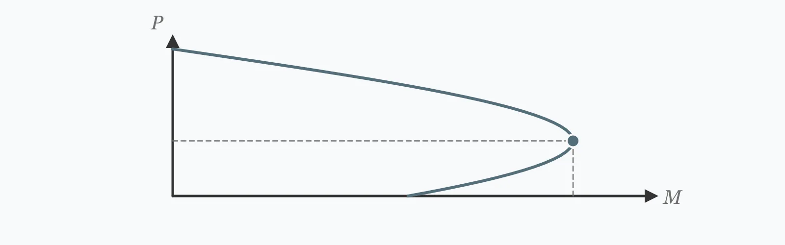
A column's moment capacity depends on how much axial load it carries, and the relationship reverses at the balanced point. Enter the section, concrete strength, steel area and yield, and the applied axial load to get the code axial capacity, the balanced axial load and moment, and the utilisation.
Calculator
Units:
mm
Perpendicular to the direction of bending
mm
In the direction of bending
MPa
Cylinder compressive strength f'c
mm²
All longitudinal bars, assumed split equally between two faces
MPa
500 MPa for standard reinforcement
kN
Design axial load, for the utilisation and region check
Calculation Result
Press Calculate for the code maximum axial capacity, the axial load and moment at the balanced point, and the percentage of axial capacity the applied load uses.
Step-by-Step Solution
Preliminary design aid. Results follow the published formulas cited
below and are intended for estimating, study and early design. Final design must be
verified by a licensed Professional Engineer against the code in force for your project.
Key Benefits
✓Gives the two defining points of the interaction diagram
✓Applies the code cap on axial capacity for accidental eccentricity
✓Identifies whether the section is compression or tension controlled
✓Warns on the steel ratio limits both minimum and maximum
✓Sensitivity chart shows the balanced moment rising with steel
✓Shareable links and CSV export for design records
What Is Column Interaction?
An interaction diagram plots every combination of axial load and moment a column section can carry. Its two anchoring features are the pure axial capacity at the top and the balanced point partway down. The balanced point is where the concrete reaches its crushing strain at the same instant the tension steel reaches yield, and it is where the section carries its greatest moment.
Why the diagram bulges outward
Below the balanced point the section is tension controlled: the steel yields first and the failure is ductile. Adding axial compression delays that yielding, so the moment capacity rises with load. Above the balanced point the concrete crushes first, the failure is brittle, and further axial load reduces the moment capacity. The curve therefore reaches its maximum moment at the balanced point rather than at zero axial load.
The code cap on axial capacity
The theoretical squash load assumes a perfectly concentric load, which no real column has. Codes therefore cap the usable axial capacity below it — 0.80 of squash for a tied column — to account for the accidental eccentricity that construction tolerance always produces. For the worked section that takes 5,598 kN down to 4,479 kN before any design moment is considered.
Formula
P₀ = 0.85·f'c·(Ag − As) + fy·As
Squash load — the theoretical concentric axial capacity
Related Formulas
P_max = 0.80 · P₀
c_b = [600 / (600 + fy)] · d
M_b = C_c(h/2 − a/2) + T(d − h/2) + C_s(h/2 − d')
Variable Definitions
Symbol
Variable
Unit
Description
b × h
Section
mm
Column width and depth. Depth is measured in the direction of bending.
f'c
Concrete Strength
MPa
Cylinder compressive strength.
As
Steel Area
mm²
Total longitudinal reinforcement, assumed split equally between two faces.
fy
Steel Yield
MPa
Reinforcement yield strength, typically 500 MPa.
P_b
Balanced Axial
kN
Axial load at which concrete crushing and steel yielding coincide.
M_b
Balanced Moment
kN·m
The greatest moment the section can carry, occurring at the balanced point.
How to Use This Calculator
Enter the depth in the direction of bendingFor biaxial bending the section has to be checked about each axis separately, and then combined. A square column is symmetric, but a rectangular one has quite different capacities in the two directions.
Enter the total longitudinal steelThis calculation assumes it splits equally between two opposite faces, which is the usual arrangement for uniaxial bending. Bars distributed around all four faces behave a little differently, and the difference grows with the number of intermediate bars.
Check the applied axial against the balanced pointAbove it the section is compression controlled and adding axial load reduces the moment capacity. Below it the reverse holds. That determines which load combination is critical for the moment check.
Keep the steel ratio between 1% and 4%The minimum exists to resist accidental moments and prevent sudden failure when the concrete cracks. The maximum is practical rather than structural — above 4% the bars congest the section and lap splices become impossible to accommodate.
Treat this as two points, not the whole diagramA full check plots the complete interaction curve and confirms the applied axial-moment pair lies inside it. Slender columns also need second-order effects, which amplify the moment and can govern entirely.
Worked Examples
Example 1
A 400 × 400 mm column in 30 MPa concrete with 3,200 mm² of 500 MPa reinforcement, carrying 1,500 kN of axial load.
Step-by-Step Solution
Gross area: 400 × 400 = 160,000 mm², so the steel ratio is 2.00%
Balanced compression block: a = 0.836 × 196.4 = 164.1 mm
Balanced axial load: 1,674 kN
Balanced moment: 453.4 kN·m — the greatest moment this section can carry
Applied 1,500 kN is 33.5% of the axial capacity and below the balanced load of 1,674 kN, so the section is tension controlled: adding axial load here would increase its moment capacity
Example 2
The same section with different reinforcement, showing what does and does not respond to it.
Both capacities rise linearly with steel — every 800 mm² adds 64 kN·m of balanced moment and about 304 kN of axial capacity.
But the balanced axial load stays at 1,674 kN in every case. It is fixed by strain compatibility — where the neutral axis sits when concrete crushing and steel yielding coincide — and that depends on the section depth and the steel yield strength, not on how much steel is there.
Quadrupling the steel from 1% to 4% raises the balanced moment by 118% and the axial capacity by only 47%. Reinforcement is far more effective at carrying moment than at carrying axial load, because the concrete already does most of the latter.
That is worth remembering when a column is failing: if the deficiency is in moment, more steel helps considerably; if it is in axial load, a larger section usually helps more.
Reinforcement Sensitivity
Both the axial capacity and the balanced moment rise linearly with steel area, but the balanced axial load does not move at all — it is fixed by strain compatibility, not by how much steel is present. The marker shows your current steel area.
Balanced Moment vs Total Steel Area
Recomputed live from your inputs. The marker shows your current value.
Line chart of Balanced Moment against Total Steel Area. The same
values are listed in the data table below.
Values plotted above, sampled across the total steel area range.
How to Interpret Your Results
The axial capacity is the ceiling. The balanced point tells you which side of the diagram the column is working on, and therefore whether more axial load helps or hurts the moment check.
Axial Utilisation: < 40Lightly loaded axially
At your result% of axial capacity the column has substantial reserve. Where the applied load is also below the balanced point, the section is tension controlled and its failure mode would be ductile — the preferred behaviour.
Axial Utilisation: 40 – 75Normal working range
At your result% of axial capacity the column is working reasonably. Check the moment at both the maximum and the minimum axial load, since which one governs depends on where each sits relative to the balanced point.
Axial Utilisation: 75 – 100Heavily loaded
At your result% of axial capacity there is little reserve for moment. Well above the balanced point the moment capacity falls steeply with further axial load, so even a modest moment may take the section outside the interaction curve.
Axial Utilisation: ≥ 100Over axial capacity
The applied load of your result% exceeds the code maximum before any moment is considered. The section is inadequate on axial load alone — enlarge it, increase the concrete grade, or add reinforcement.
Balanced Moment: ≥ 0The maximum moment available
The balanced moment of your result kN·m is the greatest this section can carry, and it occurs at the balanced axial load rather than at zero. A column with no axial load carries considerably less moment than one loaded to the balanced point.
Common Mistakes to Avoid
Assuming moment capacity falls as axial load rises
Why it matters:It only does above the balanced point. Below it, compression delays the tension steel yielding and the moment capacity increases with axial load — which is why the interaction diagram bulges outward rather than sloping down from the top.
✓How to avoid it:Compare the applied axial against the balanced load. Below it, the minimum axial load case is the critical one for moment.
Checking only the maximum load combination
Why it matters:A column above the balanced point has its lowest moment capacity at maximum axial load, but one below the balanced point has its lowest at minimum axial load. The combination that looks least severe can be the governing one.
✓How to avoid it:Check both extremes of axial load with their associated moments. Wind uplift cases with reduced axial load frequently govern in tension-controlled columns.
Using the squash load as the capacity
Why it matters:The theoretical squash load assumes perfect concentricity, which construction tolerance never delivers. Codes cap the usable capacity at 0.80 of it for tied columns — 4,479 kN against 5,598 kN in the worked example.
✓How to avoid it:Apply the code factor. It is not a safety factor but an allowance for the accidental eccentricity that always exists.
Adding steel to fix an axial deficiency
Why it matters:Reinforcement is far more effective at moment than at axial load. Quadrupling the steel from 1% to 4% raised the balanced moment by 118% but the axial capacity by only 47%, because the concrete already carries most of the axial load.
✓How to avoid it:Enlarge the section or raise the concrete grade for an axial deficiency, and add steel for a moment deficiency. The two problems have different remedies.
Ignoring slenderness
Why it matters:A slender column deflects under load, and the axial force acting through that deflection adds a second-order moment. On a slender column this amplification can exceed the first-order moment entirely, and no section check reveals it.
✓How to avoid it:Check the slenderness ratio and apply moment magnification or a second-order analysis where required. Section capacity is necessary but not sufficient for a slender column.
Treating biaxial bending as two independent checks
Why it matters:A column bent about both axes simultaneously is not adequately checked by verifying each axis alone. The combined capacity is less than either individual capacity suggests, and the interaction is not linear.
✓How to avoid it:Use a biaxial interaction check — the load contour method or a full three-dimensional interaction surface. Corner columns almost always need it.
Practical Applications
▸Checking reinforced concrete column capacity
▸Locating the balanced point of a section
▸Determining whether a column is compression or tension controlled
▸Comparing reinforcement options for moment capacity
▸Screening column sizes during scheme design
▸Assessing an existing column against revised loading
Industry Use Cases
Building frame design
Columns are checked at several load combinations because which governs depends on where each sits relative to the balanced point. Wind cases with reduced axial load frequently govern lower-storey columns that are tension controlled under those combinations.
Seismic design
Ductility requires the column to be tension controlled, so codes limit the axial load ratio explicitly — often to a fraction of the squash load. A column above the balanced point fails by concrete crushing with no warning, which is the opposite of what seismic design needs.
Assessment and strengthening
Adding reinforcement to an existing column raises the moment capacity far more than the axial. Where the deficiency is axial, jacketing to enlarge the section or increase confinement is the more effective intervention.
Expert Tips
💡Moment capacity peaks at the balanced point, not at zero axial load.
💡Below the balanced point, more axial load increases moment capacity.
💡The balanced axial load does not depend on how much steel is present.
💡Codes cap axial capacity at 0.80 of squash for accidental eccentricity.
💡Steel is far more effective for moment than for axial capacity.
💡Check both the maximum and minimum axial load combinations.
Advantages & Limitations
Advantages
✓Gives the two defining points of the interaction diagram
✓Applies the code cap rather than reporting the theoretical squash load
✓Identifies compression against tension control, which changes the design logic
✓Warns on both the minimum and maximum steel ratio limits
✓Fast enough to compare sections and reinforcement during scheme design
Limitations
!Gives two points, not the complete interaction curve
!Assumes steel split equally between two opposite faces
!Uniaxial bending only — biaxial needs a combined check
!Takes no account of slenderness or second-order effects
!Assumes a tied column; spiral columns use a higher code factor
!Uses nominal capacities without strength reduction factors
!Does not check shear, confinement or detailing requirements
What Reinforcement Changes and What It Does Not
A 400 × 400 mm column in 30 MPa concrete with 500 MPa steel. Two of the three capacities respond to the reinforcement; one does not respond at all.
400 × 400 mm, f'c = 30 MPa, fy = 500 MPa. Quadrupling the steel raises the balanced moment by 118% and the axial capacity by only 47%. The balanced axial load is unmoved at 1,674 kN throughout, because it is set by strain compatibility — section depth and steel yield — rather than by steel quantity.
A plot of every combination of axial load and moment a column section can carry. Its two defining features are the pure axial capacity at the top and the balanced point, where the section carries its greatest moment.
What is the balanced point?
The condition where the concrete reaches its crushing strain at the same instant the tension steel reaches yield. It is where the moment capacity is greatest, and it separates compression-controlled behaviour from tension-controlled.
Does more axial load always reduce moment capacity?
No — only above the balanced point. Below it, compression delays the tension steel yielding, so moment capacity increases with axial load. That is why the diagram bulges outward.
Which load combination governs a column?
It depends on where the axial load sits relative to the balanced point. Above it, maximum axial load is critical; below it, minimum axial load is. Both extremes need checking.
Why is axial capacity capped below the squash load?
Because no real column is perfectly concentrically loaded. Codes apply 0.80 for tied columns to cover the accidental eccentricity construction tolerance produces — 4,479 kN against a theoretical 5,598 kN in the example.
Does adding steel increase axial capacity much?
Less than you might expect. Quadrupling the reinforcement from 1% to 4% raised the axial capacity by 47% but the balanced moment by 118%, because the concrete already carries most of the axial load.
Why does the balanced axial load not change with steel area?
Because it is set by strain compatibility — where the neutral axis lies when crushing and yielding coincide — which depends on the section depth and the steel yield strength, not on how much steel is present.
What steel ratio should a column have?
Between 1% and 4%. The minimum resists accidental moments and prevents sudden failure at cracking; the maximum is practical, since above 4% the bars congest the section and laps cannot be accommodated.
What is compression-controlled failure?
Failure by concrete crushing before the tension steel yields — brittle, with no warning. Tension-controlled failure has the steel yielding first, which is ductile and visible, and is what seismic design requires.
Do I need to check slenderness separately?
Yes. A slender column deflects under load and the axial force acting through that deflection adds a second-order moment that can exceed the first-order one. A section check alone will not reveal it.
Glossary
Interaction diagram
The locus of axial load and moment combinations a section can carry.
Balanced point
Where concrete crushing and tension steel yielding occur simultaneously.
Squash load
The theoretical concentric axial capacity, before the code cap.
Compression controlled
Failure by concrete crushing before the steel yields — brittle.
Tension controlled
Failure with the steel yielding first — ductile and preferred.
Steel ratio
Longitudinal reinforcement area divided by gross section area.
Beta-one
The factor converting neutral axis depth to equivalent compression block depth.
Accidental eccentricity
The unintended load offset construction tolerance produces, covered by the code cap.
Second-order moment
Additional moment from axial load acting through the column's own deflection.
Biaxial bending
Bending about both axes at once, needing a combined interaction check.
Scientific & Standards References
ACI 318 — Building Code Requirements for Structural Concrete, Chapter 22: Sectional Strength — American Concrete Institute
EN 1992-1-1 (Eurocode 2) §5.8 and §6.1 — Second order effects and bending with axial force — CEN
Park, R. and Paulay, T., Reinforced Concrete Structures — Wiley
Institution of Structural Engineers — Manual for the design of concrete building structures to Eurocode 2 — Institution of Structural Engineers
MacGregor, J. G. and Wight, J. K., Reinforced Concrete: Mechanics and Design — Pearson
Conclusion
A column has no single moment capacity — it has an interaction curve, and the balanced point is where that curve reaches its maximum. Below the balanced load the section is tension controlled and adding axial compression increases the moment it can carry; above it the relationship inverts. That is why both extremes of axial load need checking, and why a wind case with reduced axial load frequently governs a column that looked comfortable at full load. The reinforcement study above shows something else worth carrying: quadrupling the steel from 1% to 4% raised the balanced moment by 118% but the axial capacity by only 47%, while the balanced axial load did not move at all — it is fixed by strain compatibility rather than by steel quantity. So steel is the remedy for a moment deficiency and a larger section for an axial one. Two checks sit outside this calculation and often govern: slenderness, which adds second-order moment that no section check reveals, and biaxial bending, where verifying each axis separately is not sufficient.
Enter your section, reinforcement and axial load above to locate the balanced point.