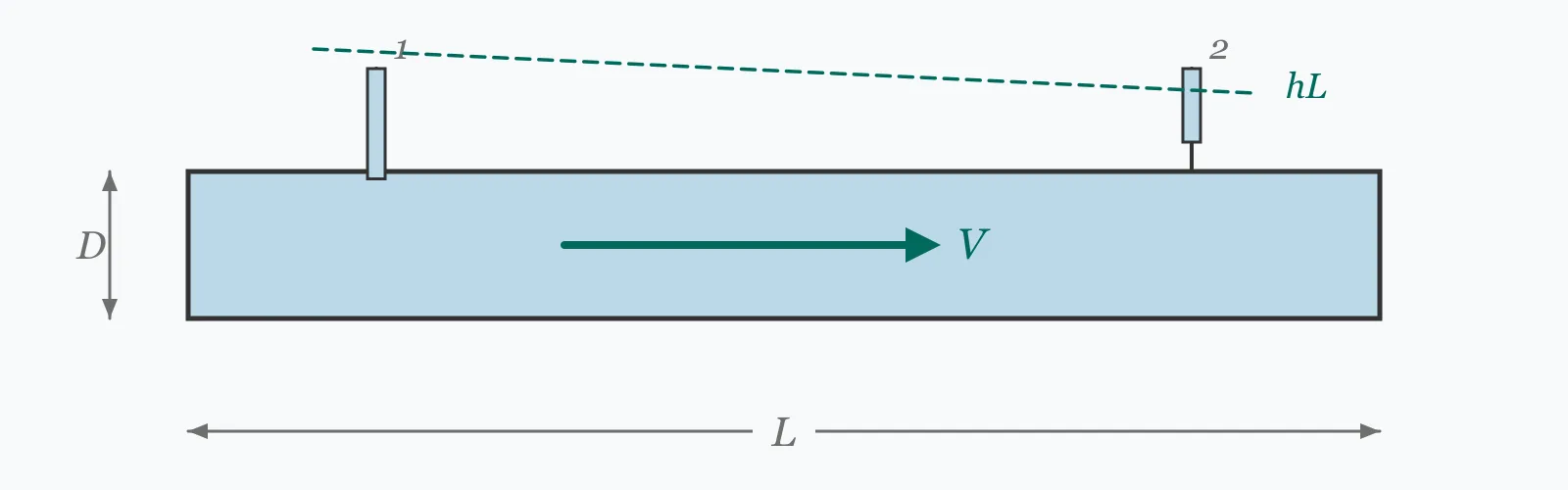
Bernoulli's equation says total energy is conserved along a streamline: pressure head plus velocity head plus elevation head, less whatever friction removes. Enter the upstream pressure, both velocities, both elevations and the head loss, and this calculator returns the downstream pressure and the total head at each point.
Calculator
Units:
kPa
Gauge pressure at the upstream point
m/s
Mean velocity at the upstream section
m
Height above your chosen datum
m/s
Mean velocity at the downstream section
m
Height above the same datum
m
Friction and fitting losses between the two points
Calculation Result
Press Calculate for the downstream pressure, the total head at each point and the downstream pressure head. Total head at point 2 should equal total head at point 1 minus the head loss — that identity is the check the calculation rests on.
Step-by-Step Solution
Preliminary design aid. Results follow the published formulas cited
below and are intended for estimating, study and early design. Final design must be
verified by a licensed Professional Engineer against the code in force for your project.
Key Benefits
✓Applies the energy equation including the head loss term
✓Returns the total head at both points, so the energy balance is visible
✓Separates pressure head from the pressure itself, which is what the grade line plots
✓Warns implicitly of cavitation risk through low or negative downstream pressure
✓Sensitivity chart shows how downstream pressure responds to velocity
✓Shareable links and CSV export for hydraulic calculations
What Is Bernoulli Equation?
Written as heads — energies per unit weight, all with units of metres — Bernoulli's equation states that P/γ + V²/2g + z is constant along a streamline. Each term is a form of energy the fluid carries: pressure head from the pressure it is under, velocity head from its motion, and elevation head from its height. For real flow the equation gains a loss term, becoming P₁/γ + V₁²/2g + z₁ = P₂/γ + V₂²/2g + z₂ + hL.
Why the three heads trade against each other
Because the total is fixed, anything that increases one term must reduce another. Water accelerating through a contraction gains velocity head and loses pressure head — the basis of the venturi meter and the reason a partly closed valve can cavitate downstream of it. Water climbing gains elevation head and loses pressure. This exchange is entirely reversible in the absence of friction, which is why an ideal fluid returning to its original height and speed also returns to its original pressure.
The head loss term is the whole difference
Ideal Bernoulli conserves total head exactly. Real flow does not: friction and turbulence convert mechanical energy into heat, and that energy never comes back. Head loss is therefore always positive and always in the direction of flow, which is what makes the hydraulic grade line slope downwards. Getting its sign wrong — subtracting it upstream instead of downstream — is the most common error in applying the equation.
Formula
P₁/γ + V₁²/2g + z₁ = P₂/γ + V₂²/2g + z₂ + h_L
Energy equation between two points in a flow system, with head loss
Related Formulas
H = P/γ + V²/2g + z
H₂ = H₁ − h_L
HGL = P/γ + z
P₂ = γ(H₁ − V₂²/2g − z₂ − h_L)
Variable Definitions
Symbol
Variable
Unit
Description
P
Pressure
kPa
Static gauge pressure at the point of interest.
V
Velocity
m/s
Mean flow velocity at the section.
z
Elevation
m
Height above an arbitrary datum. Only the difference between points matters.
h_L
Head Loss
m
Energy dissipated by friction and fittings between the two points. Always positive.
γ
Specific Weight
kN/m³
9.81 for water. Divides pressure to give pressure head in metres.
H
Total Head
m
The sum of the three heads — the quantity the equation conserves less losses.
How to Use This Calculator
Use the same datum for both elevationsOnly the difference between z₁ and z₂ affects the result, so the datum is arbitrary — but it must be the same for both points. Mixing a local datum with a site level is a common slip.
Enter gauge pressures consistentlyUse gauge pressure at both points, or absolute at both. Mixing them shifts the result by one atmosphere, about 101 kPa or 10.3 m of water.
Get the head loss from a separate calculationThis equation accounts for head loss but does not compute it. Obtain it from Darcy-Weisbach for the pipe friction, plus equivalent lengths or K-factors for the fittings between the two points.
Check the total head identityTotal head at point 2 must equal total head at point 1 minus the head loss. The calculator returns both, so the identity is directly visible — if it does not hold, an input is inconsistent.
Watch for low or negative downstream pressureA pressure head below about −7 m of water means the absolute pressure has approached the vapour pressure, and the liquid will cavitate. The equation happily returns negative pressures that no real liquid can sustain.
Worked Examples
Example 1
Water flows from point 1 at 200 kPa, 2 m/s, 10 m elevation, to point 2 at 3 m/s and 5 m elevation, losing 0.5 m of head between them. Find the downstream pressure.
Step-by-Step Solution
Pressure head at 1: P₁/γ = 200 / 9.81 = 20.387 m
Velocity head at 1: V₁²/2g = 2² / (2 × 9.81) = 4 / 19.62 = 0.204 m
Total head at 1: H₁ = 20.387 + 0.204 + 10 = 30.591 m
Check: H₂ = 24.633 + 0.459 + 5 = 30.091 m, which is H₁ − 0.5 exactly — the energy balance closes.
Note the pressure has risen from 200 to 241.6 kPa despite the friction loss, because the 5 m drop in elevation released more energy than the acceleration and friction consumed.
Example 2
A venturi contraction: the same upstream conditions, but the pipe narrows so the velocity rises from 2 to 12 m/s at the same elevation, with 0.2 m of loss. This is the effect that makes flow measurement possible and pumps cavitate.
Step-by-Step Solution
Total head at 1 is unchanged: H₁ = 30.591 m
Velocity head at 2: 12² / 19.62 = 144 / 19.62 = 7.339 m
Elevation is unchanged, so z₂ = 10 m
Pressure head at 2: 30.591 − 7.339 − 10 − 0.2 = 13.052 m
Downstream pressure: 13.052 × 9.81 = 128.0 kPa
The pressure has fallen from 200 to 128 kPa purely from the acceleration — 72 kPa converted into velocity head.
This is precisely how a venturi meter works: measure the pressure difference across a known contraction and the flow rate follows.
It is also why pump suctions cavitate. Push the velocity to 20 m/s and the pressure head falls to essentially zero — atmospheric, with nothing left in reserve. Any further increase takes it negative, and the calculation keeps going into territory a real liquid answers by boiling.
Downstream Velocity Sensitivity
Downstream pressure falls with the square of downstream velocity, because the energy has to come from somewhere and velocity head is what grows. Watch where the pressure curve crosses zero — beyond that, the calculation is predicting sub-atmospheric pressure and cavitation. The marker shows your current velocity.
Downstream Pressure (P₂) vs Downstream Velocity (V₂)
Recomputed live from your inputs. The marker shows your current value.
Line chart of Downstream Pressure (P₂) against Downstream Velocity (V₂). The same
values are listed in the data table below.
Values plotted above, sampled across the downstream velocity (v₂) range.
How to Interpret Your Results
The downstream pressure is the answer, but the pressure head is the number that tells you whether it is physically achievable. Below roughly −7 m of water, a real liquid cavitates rather than sustaining the tension.
Pressure Head at Point 2: < 0Negative pressure — cavitation likely
A downstream pressure head of your result m is below atmospheric. Water cannot sustain much tension: once absolute pressure reaches vapour pressure, around −10 m gauge at ambient temperature, it boils. Expect cavitation damage, noise and loss of flow. Reduce the velocity or raise the upstream pressure.
Pressure Head at Point 2: 0 – 5Low downstream pressure
A pressure head of your result m is low. Any further velocity increase, elevation gain or friction will take it negative, and pump suction lines in this range are close to cavitating. Check the available NPSH if a pump is downstream.
Pressure Head at Point 2: 5 – 60Normal operating range
A pressure head of your result m is comfortable for ordinary distribution and process pipework, equivalent to roughly your result metres of static water column above the point.
Pressure Head at Point 2: ≥ 60High pressure — check the rating
A pressure head of your result m exceeds 6 bar. Confirm the pipe, fittings and valves are rated for it, and remember that a surge on rapid valve closure adds substantially on top of this static value.
Total Head at Point 2: ≥ 200High total head system
A total head of your result m indicates a high-head system — tall building risers, long rising mains or high-pressure process circuits. Pressure zoning is usually required, since a single zone at this head exceeds most fitting ratings at its base.
Common Mistakes to Avoid
Adding the head loss to the downstream side instead of subtracting energy
Why it matters:Head loss always reduces the energy available downstream. Applying it with the wrong sign makes the downstream pressure higher than it should be, which is unconservative for a pipe rating and wrong for a pump duty.
✓How to avoid it:Write the equation with hL on the downstream side of the equals sign, as this calculator does. Total head must always fall in the direction of flow.
Mixing gauge and absolute pressures
Why it matters:One atmosphere is about 101 kPa, or 10.3 m of water head. Entering an absolute pressure at one point and a gauge pressure at the other shifts the whole balance by that amount.
✓How to avoid it:Use gauge pressure at both points for ordinary hydraulics. Absolute pressure is needed only for cavitation and NPSH checks, where the reference matters.
Using different datums for the two elevations
Why it matters:Only the elevation difference matters, but both must be measured from the same reference. Mixing a local datum with a site or sea level introduces an arbitrary error in metres.
✓How to avoid it:Pick one datum and use it throughout. A convenient choice is the lower of the two points, which makes one elevation zero.
Applying Bernoulli across a pump or turbine
Why it matters:The equation accounts for losses but not for energy added or removed by a machine. A pump raises total head, which a plain Bernoulli balance cannot represent.
✓How to avoid it:Add the pump head to the upstream side or the turbine head to the downstream side. The extended energy equation is H₁ + h_pump = H₂ + h_turbine + hL.
Trusting a negative pressure result
Why it matters:The algebra will happily return large negative pressures, but water cannot sustain tension. Below vapour pressure it boils, forming cavities that collapse violently and erode metal.
✓How to avoid it:Treat any result below about −7 m of gauge pressure head as a cavitation prediction rather than a pressure. Reduce velocity, lower the elevation or raise the upstream pressure.
Ignoring the velocity head where it matters
Why it matters:At ordinary pipe velocities the velocity head is small — 0.2 m at 2 m/s — and is often neglected. But it grows with the square of velocity, reaching 7.3 m at 12 m/s, which is no longer negligible.
✓How to avoid it:Include the velocity head as a matter of routine. It is cheap to compute and becomes dominant exactly where the answer matters most, in contractions and at pump suctions.
Practical Applications
▸Finding pressure at any point in a pipe network
▸Sizing pumps by establishing the required head
▸Designing and interpreting venturi and orifice flow meters
▸Checking cavitation risk at pump suctions and valve outlets
▸Verifying pressure at the top of building risers
▸Analysing flow from tanks, nozzles and outlets
Industry Use Cases
Water distribution
The hydraulic grade line is the working tool of network design: plot P/γ + z along a main and its slope is the friction gradient. Where the line falls below ground level, the pipe is under negative pressure and at risk of contamination ingress through joints.
Pump installation
Available NPSH is a Bernoulli calculation from the source liquid surface to the pump suction, including friction and velocity head, referenced to absolute pressure and vapour pressure. Getting it wrong is the single most common cause of pump cavitation.
Flow measurement
Venturi meters, orifice plates and Pitot tubes all work by converting velocity head into a measurable pressure difference. Bernoulli's equation is what converts the reading back into a flow rate, with a discharge coefficient for the real losses.
Expert Tips
💡Total head always falls in the direction of flow, by exactly the head loss — use it as a check.
💡Velocity head is small at ordinary velocities but grows with the square: 0.2 m at 2 m/s, 7.3 m at 12 m/s.
💡For water, 1 m of head is 9.81 kPa, and one atmosphere is 10.3 m.
💡The hydraulic grade line is P/γ + z; where it drops below ground, the pipe is in suction.
💡Any result below about −7 m of pressure head is a cavitation prediction, not a pressure.
💡Pumps and turbines are not losses — add them as separate terms in the extended energy equation.
Advantages & Limitations
Advantages
✓Complete energy accounting between any two points in a system
✓Returns the total head at both points, making the balance verifiable
✓Separates pressure head from pressure, matching how grade lines are plotted
✓Applies to any incompressible fluid through the specific weight
✓Simple enough to check by hand during design review
Limitations
!Accounts for head loss but does not compute it — that requires Darcy-Weisbach or equivalent
!Does not represent pumps or turbines, which add or remove energy
!Assumes incompressible flow, so it is not valid for gases at high velocity
!Assumes steady flow; surge and water hammer are separate transient problems
!Uses mean velocity, ignoring the kinetic energy correction factor of the real profile
!Returns negative pressures that no real liquid can sustain
!Assumes water density unless the specific weight is adjusted
How Downstream Pressure Responds
Starting from the same upstream condition — 200 kPa, 2 m/s, 10 m elevation — with 0.5 m of head loss throughout. Each row changes one thing, showing how the three heads trade against one another.
Upstream: 200 kPa, 2 m/s, 10 m. Head loss 0.5 m in every case. The final row is a cavitation prediction, not an achievable pressure.
A statement that total energy is conserved along a streamline. In head form: P/γ + V²/2g + z is constant, less any head loss. The three terms are pressure head, velocity head and elevation head, all measured in metres of fluid.
What is total head?
The sum of pressure, velocity and elevation heads at a point — the total mechanical energy per unit weight of fluid. It always falls in the direction of flow, by exactly the head loss between the two points.
Why does pressure drop when a pipe narrows?
Because total energy is fixed. A contraction speeds the flow, which raises the velocity head, and that energy has to come from the pressure head. This is the venturi effect, and it is why flow meters and pump cavitation both work the way they do.
How do I convert pressure to head?
Divide by the specific weight: for water, head in metres equals pressure in kPa divided by 9.81. So 200 kPa is 20.4 m of water, and conversely 1 m of head is 9.81 kPa.
What is the hydraulic grade line?
A plot of P/γ + z along a pipeline — total head minus the velocity head. It shows the level water would rise to in a standpipe at each point, and where it falls below the pipe, the pipe is under negative pressure.
Does Bernoulli's equation work for a pump?
Not directly. A pump adds energy, which plain Bernoulli cannot represent. Use the extended energy equation H₁ + h_pump = H₂ + h_turbine + hL, adding the pump head on the upstream side.
What happens if the calculated pressure is negative?
It means the flow cannot happen as specified. Water cannot sustain tension: once absolute pressure reaches vapour pressure, it boils, forming cavities that collapse violently and erode metal. Treat negative results as cavitation predictions.
Why does head loss always reduce the total head?
Because friction converts mechanical energy into heat, which the flow cannot recover. That irreversibility is why head loss is always positive and always acts in the direction of flow — the hydraulic grade line only ever slopes downwards.
Is velocity head significant in real systems?
It depends on the velocity. At 2 m/s it is only 0.2 m and often neglected. At 12 m/s it is 7.3 m, which dominates. Since it grows with the square of velocity, it matters most exactly where the pressure result is most critical.
Can I use this for air or gas?
Only at low velocity, below roughly Mach 0.3, where compressibility can be ignored. Above that, density changes with pressure and the compressible flow equations are needed instead.
Glossary
Total head
The sum of pressure, velocity and elevation heads — total mechanical energy per unit weight of fluid.
Pressure head
Pressure divided by specific weight, P/γ, expressed as a height of fluid.
Velocity head
The quantity V²/2g, the kinetic energy per unit weight expressed as a height.
Elevation head
Height above a chosen datum, representing potential energy per unit weight.
Head loss
Mechanical energy converted irreversibly to heat by friction and turbulence.
Hydraulic grade line
A plot of pressure head plus elevation along a system, showing where water would stand in a standpipe.
Energy grade line
A plot of total head along a system, always above the hydraulic grade line by the velocity head.
Cavitation
Formation and violent collapse of vapour cavities when local pressure falls to the liquid's vapour pressure.
Venturi effect
The pressure drop accompanying acceleration through a contraction, exploited for flow measurement.
NPSH
Net positive suction head — the absolute pressure head available at a pump suction above vapour pressure.
Scientific & Standards References
Bernoulli, D., Hydrodynamica (1738) — Strasbourg, 1738
White, F. M., Fluid Mechanics, 8th Edition — Chapter 3: Integral Relations for a Control Volume — McGraw-Hill
Crane Technical Paper No. 410 — Flow of Fluids Through Valves, Fittings and Pipe — Crane Co.
ISO 5167 — Measurement of fluid flow by means of pressure differential devices — International Organization for Standardization
Hydraulic Institute Standards — NPSH Margin for Rotodynamic Pumps — Hydraulic Institute
Conclusion
Bernoulli's equation is energy accounting: pressure head, velocity head and elevation head trade freely against one another, and head loss removes energy permanently in the direction of flow. The identity worth using as a check is that total head at the downstream point equals total head upstream minus the loss — if it does not, an input is inconsistent. Two practical cautions follow. Velocity head is negligible at 2 m/s and dominant at 12 m/s, so neglecting it is safe until exactly the moment it stops being. And the algebra will return pressures below anything a real liquid can sustain: below about −7 m of head, the honest reading is not a pressure but a prediction of cavitation.
Try your own two points above, then sweep the downstream velocity in the chart to see where the pressure crosses zero.