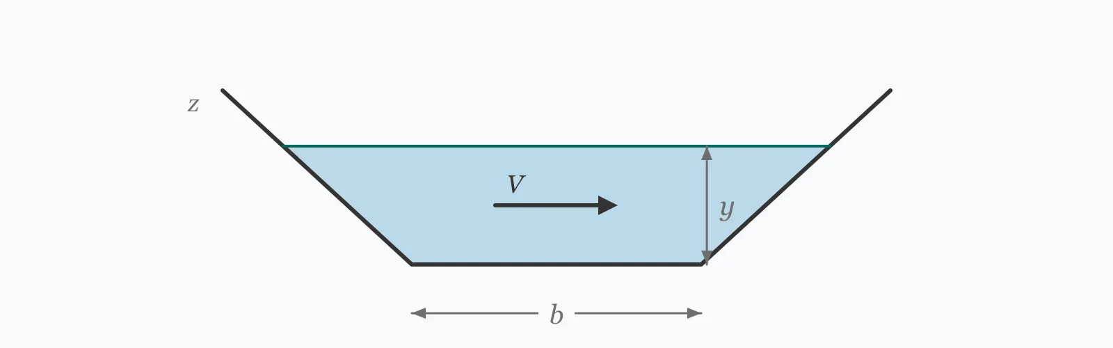
Manning's equation gives the velocity in an open channel from its shape, slope and roughness: V = (1/n)·R^(2/3)·S^(1/2). Enter the bottom width, depth, side slope, channel slope and Manning's n for a trapezoidal section to get the velocity, the discharge, the hydraulic radius, and the Froude number computed on hydraulic depth. The result is checked against the velocities at which channels silt up and erode.
Calculator
Units:
m
Width of the channel invert. Enter 0 for a triangular section
m
Depth of flow, not the full channel depth
H:1V
Firm earth 1.5, sand 2 to 3, lined channels can be steeper. 0 for rectangular
m/m
Longitudinal bed slope, as a decimal. 0.002 is 1 in 500
Press Calculate for the velocity, discharge, hydraulic radius and Froude number. The velocity is checked against the 0.6 m/s self-cleansing minimum and the erosion limits for unlined and lined channels.
Step-by-Step Solution
Preliminary design aid. Results follow the published formulas cited
below and are intended for estimating, study and early design. Final design must be
verified by a licensed Professional Engineer against the code in force for your project.
Key Benefits
✓Handles the trapezoidal section that most designed channels actually use
✓Computes the Froude number on hydraulic depth A/T, not maximum depth
✓Checks the velocity against silting and scour limits automatically
✓Warns when the flow strays close to critical, where the surface is unstable
✓Sensitivity chart shows how weakly velocity responds to depth
✓Shareable links and CSV export for design records
What Is Open Channel Velocity?
Manning's equation relates the mean velocity in an open channel to three things: the hydraulic radius, which describes the shape; the bed slope, which supplies the driving energy; and the roughness coefficient n, which resists it. V = (1/n)·R^(2/3)·S^(1/2). It is an empirical formula, fitted to observation rather than derived, but it has proved robust enough across a century of use that it remains the standard tool for uniform open channel flow.
Why the trapezoidal section dominates
Excavated channels are trapezoidal because vertical earth sides collapse. The side slope is set by the material — around 1.5 horizontal to 1 vertical for firm earth, flatter for sand, steeper only where the channel is lined. The shape enters through the hydraulic radius, the flow area divided by the wetted perimeter, which measures how efficiently the section carries water relative to the boundary it has to drag against.
The velocity window
Channel design is bounded on both sides. Below roughly 0.6 m/s, suspended material settles and the channel gradually fills, which is why drainage channels carry a self-cleansing minimum. Above the erosion limit, the bed and banks are progressively cut away — about 0.8 m/s for unlined earth, 1.5 m/s for grass lining, and several metres per second for concrete. Choosing a lining is therefore as much a hydraulic decision as a cost one, because it sets the upper bound of the window.
Formula
V = (1/n) · R^(2/3) · S^(1/2)
Manning's equation for mean velocity in uniform open channel flow (metric form)
Related Formulas
A = (b + z·y) · y
P = b + 2y·√(1 + z²)
R = A / P
Fr = V / √(g · A/T)
Variable Definitions
Symbol
Variable
Unit
Description
V
Mean Velocity
m/s
Cross-sectional average velocity under uniform flow.
n
Manning's Roughness
s/m^⅓
Resistance coefficient. Concrete 0.013, earth 0.025, weedy channel 0.05 or more.
R
Hydraulic Radius
m
Flow area divided by wetted perimeter.
S
Channel Slope
m/m
Bed slope. Velocity depends on its square root, so it is a weak lever.
b
Bottom Width
m
Width of the channel invert.
z
Side Slope
H:1V
Horizontal run per unit of vertical rise on the banks.
How to Use This Calculator
Choose Manning's n with careIt is the most influential input and the least precisely known. Velocity is inversely proportional to it, so the difference between a clean earth channel at 0.025 and a weedy one at 0.05 is a factor of two in velocity and discharge. Design for the maintained condition and check the overgrown one.
Enter the flow depth, not the channel depthManning's equation describes the flow, so the depth is the water depth at the design condition, not the excavated depth. Freeboard is added afterwards, typically 0.3 m or a quarter of the flow depth, whichever is greater.
Set the side slope from the soilAround 1.5 horizontal to 1 vertical suits firm earth; sand needs 2 or 3 to 1; rock or lined channels can be steeper. Side slopes flatter than the soil will stand at are not a conservatism but a requirement — the bank will find its own angle otherwise.
Check the velocity against both limitsBelow about 0.6 m/s the channel will silt and need clearing. Above the erosion limit for the lining, it will scour. The calculator warns at both ends; the acceptable window is narrower than most designs assume.
Confirm the flow is not near criticalA Froude number near 1 means an unstable water surface with standing waves. This is easy to stumble into when a channel is lined, because reducing n raises the velocity sharply — as the second example below shows.
Worked Examples
Example 1
A trapezoidal earth drainage channel: 2.0 m bottom width, 0.8 m flow depth, side slopes 1.5 to 1, bed slope 1 in 500, Manning's n of 0.030 for a maintained earth channel.
Interpretation: at 0.97 m/s the channel is above the 0.6 m/s self-cleansing minimum but also above the 0.8 m/s at which unlined earth begins to scour. It needs a grass lining or a flatter gradient.
Example 2
The same channel lined in concrete, reducing Manning's n from 0.030 to 0.013. Nothing else changes.
Step-by-Step Solution
Area, perimeter and hydraulic radius are unchanged: 2.560 m², 4.884 m and 0.5241 m
V = (1/0.013) × 0.6501 × 0.04472 = 2.236 m/s
The velocity has risen by exactly the ratio of the roughness values: 0.030/0.013 = 2.308
Discharge: Q = 2.236 × 2.560 = 5.725 m³/s, more than double the earth channel
Fr = 2.236 / 2.389 = 0.936 — subcritical, but only just, and inside the unstable band near Fr = 1
So lining the channel has two consequences that pull in opposite directions. Capacity has more than doubled for no change in excavation, which is the reason to line it.
But the flow is now on the edge of critical, where the surface oscillates and standing waves form. The concrete easily tolerates 2.2 m/s, so scour is not the issue — instability is.
The remedy is to flatten the gradient or widen the section so the Froude number falls back below about 0.9. This is a common trap: reducing roughness looks like a free capacity gain until the flow regime is checked.
Depth Sensitivity
Discharge climbs steeply with depth while velocity rises only gently — the section gains area much faster than it gains hydraulic radius. Switch series to compare. The marker shows your current depth.
Mean Velocity vs Flow Depth (y)
Recomputed live from your inputs. The marker shows your current value.
Line chart of Mean Velocity against Flow Depth (y). The same
values are listed in the data table below.
Values plotted above, sampled across the flow depth (y) range.
How to Interpret Your Results
Velocity is the result that governs whether the channel works. It has to clear its own sediment without cutting into its own bed, and the acceptable window depends entirely on the lining.
Mean Velocity: < 0.6Below self-cleansing velocity
A velocity of your result m/s is below the 0.6 m/s usually taken as self-cleansing. Silt and organic matter will settle out, capacity will fall progressively, and the channel will need regular clearing. Steepen the gradient or narrow the section.
Mean Velocity: 0.6 – 0.8Suitable for unlined earth
A velocity of your result m/s clears sediment and stays within the roughly 0.8 m/s limit for unlined earth channels. This is the narrow window in which an unlined channel is stable in both directions.
Mean Velocity: 0.8 – 1.5Needs erosion protection
A velocity of your result m/s exceeds what unlined earth will stand but is within the roughly 1.5 m/s that grass lining tolerates. Specify a grass or riprap lining, or flatten the gradient.
Mean Velocity: 1.5 – 3Requires a hard lining
A velocity of your result m/s needs concrete, stone pitching or heavy riprap. Check the Froude number too — reducing roughness to gain capacity often pushes the flow towards critical, where the surface becomes unstable.
Mean Velocity: ≥ 3High velocity — check regime and abrasion
A velocity of your result m/s is high even for a lined channel. Verify the Froude number, since the flow is likely supercritical, and consider abrasion of the lining if the flow carries sand or gravel.
Common Mistakes to Avoid
Using an optimistic Manning's n
Why it matters:Velocity is inversely proportional to n, so the coefficient carries the calculation. A channel designed at 0.025 for clean earth that grows weeds to 0.05 loses half its capacity, and that is a maintenance state most channels reach eventually.
✓How to avoid it:Design capacity on the maintained value but check the overgrown condition too. Where maintenance cannot be assured, use the higher figure for capacity.
Checking only the upper velocity limit
Why it matters:Scour is visible and silting is gradual, so the erosion limit gets the attention. A channel that runs too slowly fills with sediment, loses capacity year on year, and eventually floods for reasons that look like a rainfall problem.
✓How to avoid it:Check both bounds. The self-cleansing minimum of about 0.6 m/s is a real design constraint, particularly on flat sites where the gradient is hard to find.
Computing the Froude number on maximum depth
Why it matters:For a trapezoidal section the hydraulic depth A/T is noticeably less than the maximum depth — 0.582 m against 0.800 m in the example above. Using the larger value understates the Froude number by about 17%.
✓How to avoid it:Use A/T, as this calculator does. The difference matters most in exactly the case where it is least welcome: a flow already close to critical.
Assuming uniform flow applies
Why it matters:Manning's equation describes uniform flow, in which depth and velocity are constant along the reach. Near a bend, a structure, a change of section or a hydraulic jump, the flow is not uniform and the equation does not apply.
✓How to avoid it:Use it for the uniform reach and treat transitions separately with an energy or momentum analysis. A backwater calculation is needed where a downstream control raises the level.
Treating slope as a strong design lever
Why it matters:Velocity depends on the square root of slope, so doubling the gradient gains only 41% more velocity. On flat sites there is often a temptation to chase gradient at considerable earthwork cost for a modest hydraulic return.
✓How to avoid it:Compare against changing the section or the lining. Roughness acts on velocity directly rather than through a square root, so a lining change is usually the more effective and cheaper lever.
Forgetting freeboard
Why it matters:The calculation gives the depth needed to carry the design flow. Building the channel to exactly that depth leaves no margin for wave action, bends, sediment accumulation or a storm larger than the design event.
✓How to avoid it:Add freeboard above the design water surface — typically 0.3 m or a quarter of the flow depth, whichever is greater, and more on bends where superelevation raises the outside level.
Practical Applications
▸Sizing trapezoidal drainage and irrigation channels
▸Checking the capacity of an existing watercourse
▸Comparing lining options by their effect on velocity and capacity
▸Verifying that a channel is self-cleansing at low flows
▸Screening for scour risk in unlined channels
▸Establishing normal depth for a backwater computation
Industry Use Cases
Land drainage
Field and highway drainage channels are sized for capacity but governed by the velocity window. On flat land the self-cleansing minimum is the binding constraint, which is why such channels are often narrower and deeper than capacity alone would require.
Irrigation
Distribution canals are lined to reduce seepage as much as to raise capacity, and the roughness change that follows more than doubles the velocity. The Froude number must be rechecked after lining, because a section that was comfortably subcritical in earth may not be in concrete.
River engineering
Natural channels have roughness that varies seasonally with vegetation, so capacity is assessed at both the summer and winter condition. A channel that conveys the design flood in February may not in August.
Expert Tips
💡Velocity is inversely proportional to n — roughness is the strongest single lever.
💡Velocity depends only on the square root of slope; doubling gradient gains 41%.
💡The workable window for unlined earth is roughly 0.6 to 0.8 m/s — very narrow.
💡Use hydraulic depth A/T for the Froude number, not the maximum depth.
💡Lining a channel more than doubles the velocity and can push it near critical.
💡Add freeboard: 0.3 m or a quarter of the flow depth, whichever is greater.
Advantages & Limitations
Advantages
✓Handles the trapezoidal section that real excavated channels use
✓Reports the Froude number correctly, on hydraulic depth rather than maximum depth
✓Checks the velocity against both the silting and the scour bound
✓Warns explicitly when a lining change pushes the flow towards critical
✓Simple and stable enough to iterate a section during scheme design
Limitations
!Assumes uniform steady flow in a prismatic channel
!Does not apply near bends, structures, transitions or hydraulic jumps
!Manning's n must be supplied and is the dominant source of uncertainty
!Assumes a single roughness for the whole perimeter, not a composite section
!Does not compute freeboard, superelevation on bends or sediment transport
!Gives normal depth behaviour only; a downstream control requires a backwater profile
!Velocity limits for silting and scour are conventional guides, not universal values
How Roughness Governs the Same Section
The same trapezoidal channel — 2.0 m bottom width, 0.8 m depth, 1.5:1 sides, 1 in 500 gradient — with only Manning's n changed. Velocity and discharge scale exactly inversely with n, so the excavation is identical and the capacity differs almost fourfold.
Identical geometry throughout; only n changes. The concrete row carries 3.85 times the discharge of the overgrown one for the same excavation — but sits at Fr 0.936, inside the unstable band. The overgrown row falls below the 0.6 m/s self-cleansing minimum, so it will silt and get worse.
An empirical formula for mean velocity in uniform open channel flow: V = (1/n)·R^(2/3)·S^(1/2), where R is the hydraulic radius, S the bed slope and n the roughness coefficient.
How do I calculate the hydraulic radius of a trapezoidal channel?
Divide the flow area by the wetted perimeter. Area is (b + zy)·y and perimeter is b + 2y√(1+z²), so a 2 m wide channel at 0.8 m depth with 1.5:1 sides gives R = 2.56/4.884 = 0.524 m.
What Manning's n should I use?
About 0.013 for smooth concrete, 0.025 for a clean earth channel, 0.035 for a natural watercourse, and 0.05 or more for a weedy or overgrown one. It is the most influential and least certain input in the calculation.
What is the minimum velocity for a drainage channel?
Around 0.6 m/s is the usual self-cleansing minimum. Below it, silt and organic matter settle out and the channel loses capacity progressively.
What velocity will erode an earth channel?
Roughly 0.8 m/s for unlined earth, about 1.5 m/s for grass lining, and several metres per second for concrete or stone. The lining choice sets the upper bound of the design window.
Why does the velocity double when I line a channel?
Because velocity is inversely proportional to Manning's n. Reducing n from 0.030 for earth to 0.013 for concrete multiplies the velocity by 0.030/0.013 = 2.31, with no change to the excavation.
What side slope should a channel have?
About 1.5 horizontal to 1 vertical for firm earth, 2 or 3 to 1 for sand, and steeper only where the channel is lined or in rock. The soil determines it, not the hydraulics.
How much freeboard should I allow?
Typically 0.3 m or a quarter of the flow depth, whichever is greater, added above the design water surface. More is needed on bends, where the water surface superelevates on the outside.
Why use hydraulic depth for the Froude number?
Because the wave celerity in a non-rectangular channel depends on A/T, area over top width, rather than the maximum depth. In the trapezoidal example above the two are 0.582 m and 0.800 m, a 17% difference in the resulting Froude number.
Does Manning's equation work for pipes?
Yes, for a pipe flowing partly or fully under gravity, using the hydraulic radius of the wetted section. For a circular pipe flowing full, R is exactly D/4.
Glossary
Manning's equation
Empirical relation for mean velocity in uniform open channel flow.
Manning's n
Roughness coefficient resisting flow; velocity is inversely proportional to it.
Hydraulic radius
Flow area divided by wetted perimeter, measuring sectional efficiency.
Wetted perimeter
The length of channel boundary in contact with the flowing water.
Trapezoidal section
A channel with a flat invert and sloping sides, the standard excavated form.
Side slope
The horizontal run per unit of vertical rise on a channel bank, written z:1.
Self-cleansing velocity
The minimum velocity, about 0.6 m/s, that keeps sediment in suspension.
Normal depth
The depth at which flow is uniform for a given discharge, slope and roughness.
Freeboard
Additional channel depth above the design water surface.
Hydraulic depth
Flow area divided by top width, A/T, used for the Froude number.
Scientific & Standards References
Manning, R., On the Flow of Water in Open Channels and Pipes, Transactions of the Institution of Civil Engineers of Ireland (1891) — Institution of Civil Engineers of Ireland
Chow, V. T., Open-Channel Hydraulics — Chapter 5: Development of Uniform Flow and Its Formulas — McGraw-Hill
USGS Water-Supply Paper 2339 — Guide for Selecting Manning's Roughness Coefficients for Natural Channels and Flood Plains — United States Geological Survey
CIRIA C689 — Culvert, Screen and Outfall Manual — Construction Industry Research and Information Association
USDA NRCS National Engineering Handbook, Part 654 — Stream Restoration Design — US Department of Agriculture
Conclusion
Manning's equation predicts channel velocity from shape, slope and roughness, and of the three the roughness coefficient does most of the work. Velocity is inversely proportional to n, so the comparison table above shows the same excavation carrying 5.73 m³/s in concrete and 1.49 m³/s once overgrown — a factor of 3.85 with no change in geometry at all. Slope, by contrast, is a weak lever: it enters as a square root, so doubling the gradient buys only 41% more velocity for a great deal more earthwork. The design is bounded on both sides, and the window is narrower than it looks — roughly 0.6 m/s to avoid silting and 0.8 m/s before unlined earth begins to scour. Lining the channel widens that window substantially, but it raises the velocity so sharply that the Froude number must be rechecked: the concrete case here sits at 0.936, subcritical only just, and inside the band where the water surface becomes unstable.
Enter your own section, gradient and lining above to size a channel.