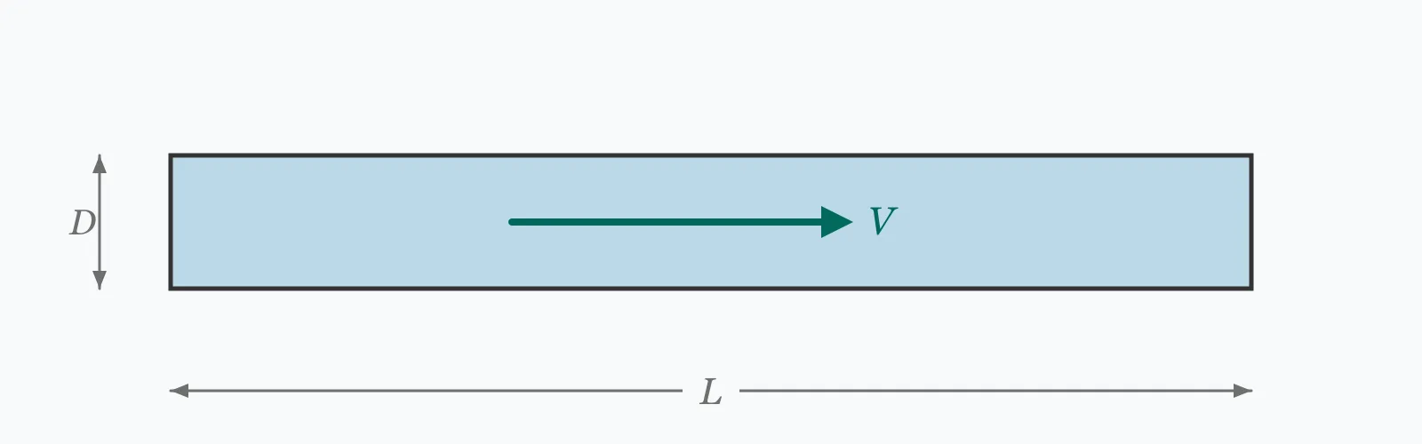
The Reynolds number is the ratio of inertial to viscous forces, Re = V·D/ν, and it decides whether flow is orderly or chaotic. Enter the velocity, internal diameter and kinematic viscosity to get the Reynolds number, the flow regime, the Darcy friction factor for that regime, and the velocity at which this pipe and fluid leave laminar flow.
Calculator
Units:
m/s
Flow rate divided by pipe area
m
Pipe bore. Use hydraulic diameter 4A/P for non-circular ducts
m²/s
Water at 20 °C is 1.004×10⁻⁶; air 1.5×10⁻⁵; SAE 30 oil 2.9×10⁻⁴
Calculation Result
Press Calculate for the Reynolds number, the flow regime, the Darcy friction factor for that regime, and the velocity at which laminar flow ends in this pipe. Below Re 2300 flow is laminar, above 4000 turbulent, and the band between is genuinely unpredictable.
Step-by-Step Solution
Preliminary design aid. Results follow the published formulas cited
below and are intended for estimating, study and early design. Final design must be
verified by a licensed Professional Engineer against the code in force for your project.
Key Benefits
✓Classifies the flow regime, which determines every downstream calculation
✓Returns the matching friction factor — exact for laminar, correlated for turbulent
✓Reports the velocity at which this specific pipe leaves laminar flow
✓Flags the transitional band rather than pretending it is predictable
✓Sensitivity chart shows the friction factor discontinuity at the threshold
✓Shareable links and CSV export for design records
What Is Reynolds Number?
The Reynolds number compares the inertia of a moving fluid against its viscosity: Re = V·D/ν, where V is the mean velocity, D the internal diameter and ν the kinematic viscosity. When viscosity dominates, disturbances are damped out and the fluid moves in orderly layers — laminar flow. When inertia dominates, disturbances grow into eddies and the flow becomes turbulent. The number is dimensionless, so a value of 74,700 means the same thing for water in a pipe as for air over a wing.
The two friction laws
In laminar flow the Darcy friction factor is exactly 64/Re — a result derived from first principles, not fitted to data. In turbulent flow it must be correlated, and it depends on pipe roughness as well as Reynolds number. The practical consequence is the exponent on velocity: laminar head loss is proportional to V, turbulent head loss to roughly V^1.75 to V². Doubling the flow in a laminar line doubles the pressure drop; doubling it in a turbulent line nearly quadruples it.
Why the transitional band is not a third regime
Between Re 2300 and 4000 the flow is not something intermediate — it is unstable. The same pipe at the same Reynolds number can run laminar or turbulent depending on inlet disturbance, vibration, and how smoothly the flow was established. Careful laboratory work has held laminar flow to Re above 10,000; a rough industrial entry may trip turbulence below 2000. Designing a system to operate in this band means accepting that its pressure drop is not predictable.
Formula
Re = V · D / ν
Reynolds number for full pipe flow, from mean velocity, internal diameter and kinematic viscosity
Related Formulas
Re = ρ · V · D / μ
f = 64 / Re
f = 0.316 / Re^0.25
V_crit = 2300 · ν / D
Variable Definitions
Symbol
Variable
Unit
Description
Re
Reynolds Number
—
Ratio of inertial to viscous forces. Dimensionless, so it compares any fluid with any other.
V
Mean Velocity
m/s
Flow rate divided by cross-sectional area, not the peak centreline velocity.
D
Internal Diameter
m
Bore of the pipe. For non-circular ducts, use the hydraulic diameter 4A/P.
ν
Kinematic Viscosity
m²/s
Dynamic viscosity divided by density. 1.004×10⁻⁶ for water at 20 °C.
f
Darcy Friction Factor
—
Coefficient in the Darcy-Weisbach head loss equation. Four times the Fanning factor.
V_crit
Critical Velocity
m/s
The velocity at which Re reaches 2300 for this pipe and fluid.
How to Use This Calculator
Use the mean velocity, not the peakReynolds number is defined on the mean velocity — volumetric flow rate divided by cross-sectional area. In laminar pipe flow the centreline velocity is twice the mean, so using it would double the result and could push a laminar flow across the threshold on paper.
Enter the internal diameterNominal pipe sizes are not bores. A DN50 steel pipe has an internal diameter closer to 52.5 mm, and a 50 mm PE100 SDR11 pipe is about 40.8 mm inside. For rectangular ducts use the hydraulic diameter, four times the area divided by the wetted perimeter.
Match the viscosity to the temperatureKinematic viscosity is strongly temperature dependent. Water falls from 1.004×10⁻⁶ m²/s at 20 °C to 3.65×10⁻⁷ at 80 °C, which nearly triples the Reynolds number at the same velocity. Use the value at the actual operating temperature.
Read the regime before anything elseThe regime determines which friction correlation applies and how head loss scales with flow. Every downstream calculation — pressure drop, pump duty, heat transfer coefficient — branches on this one result.
Treat a transitional result as a design flagIf the result falls between 2300 and 4000, the pressure drop is not predictable. Change the pipe size or the flow rate to move clear of the band rather than picking a friction factor and hoping.
Worked Examples
Example 1
Water at 20 °C flows at 1.5 m/s through a 50 mm internal diameter pipe. Kinematic viscosity is 1.004×10⁻⁶ m²/s.
Step-by-Step Solution
Re = V·D/ν = 1.5 × 0.05 / 1.004×10⁻⁶
Numerator: 1.5 × 0.05 = 0.075 m²/s
Re = 0.075 / 1.004×10⁻⁶ = 74,701
Re = 74,701 is far above 4,000, so the flow is fully turbulent
Friction factor by Blasius: f = 0.316 / 74,701^0.25 = 0.316 / 16.532 = 0.0191
Laminar limit for this pipe: V = 2300 × 1.004×10⁻⁶ / 0.05 = 0.0462 m/s
Interpretation: laminar flow in this pipe would need a velocity below 46 mm/s, which is under 0.1 L/s. Any practical water service is turbulent by a wide margin.
Example 2
The same pipe and the same velocity, but carrying SAE 30 oil with a kinematic viscosity of 2.9×10⁻⁴ m²/s — 289 times that of water.
Re = 259 is well below 2,300, so the flow is laminar
Friction factor: f = 64 / 259 = 0.2475 — thirteen times the water value of 0.0191
Laminar limit: V = 2300 × 2.9×10⁻⁴ / 0.05 = 13.34 m/s, a velocity no practical oil line would ever reach
The same geometry at the same speed gives completely different flow physics, purely because of viscosity.
A thirteen-fold friction factor does not translate into thirteen times the pressure drop in every circumstance — but it does mean the loss now scales with velocity rather than velocity squared, so the oil line responds quite differently to a change in flow.
This is why viscous fluids are handled with larger bores and lower velocities: there is no turbulent regime available to them at any sensible speed.
Velocity Sensitivity
The Reynolds number rises linearly with velocity, but the friction factor does not — it falls steeply through the laminar range, jumps at the transition, then declines slowly. Switch to the friction factor series to see the discontinuity at Re ≈ 2300. The marker shows your current velocity.
Reynolds Number vs Mean Velocity
Recomputed live from your inputs. The marker shows your current value.
Line chart of Reynolds Number against Mean Velocity. The same
values are listed in the data table below.
Values plotted above, sampled across the mean velocity range.
How to Interpret Your Results
The regime is the result that matters. It determines which friction law applies, how head loss scales with flow, and how well the fluid mixes and transfers heat.
Reynolds Number: < 2300Laminar flow
Re = your result is below 2,300, so the flow is laminar. The friction factor is exactly 64/Re, head loss is proportional to velocity rather than velocity squared, and there is almost no radial mixing — which makes heat transfer poor and any dissolved constituent slow to disperse.
Reynolds Number: 2300 – 4000Transitional — not predictable
Re = your result falls in the transitional band. This is not a third regime but an unstable one: the flow may be laminar or turbulent and can switch between them, so the pressure drop cannot be predicted reliably. Change the pipe size or the flow rate to move clear of it.
Reynolds Number: 4000 – 100000Turbulent flow
Re = your result is turbulent, which covers almost all practical water and gas pipework. Head loss scales close to velocity squared, mixing is vigorous and heat transfer is good. The friction factor shown assumes a hydraulically smooth pipe — commercial roughness raises it.
Re = your result is high enough that pipe roughness, not Reynolds number, governs the friction factor. The smooth-pipe value shown is a lower bound; use the Colebrook equation or a Moody chart with the actual relative roughness for anything but a preliminary estimate.
Common Mistakes to Avoid
Using dynamic viscosity where kinematic is required
Why it matters:The two differ by the density, a factor of about 1000 for water. Substituting μ = 1.002×10⁻³ Pa·s for ν = 1.004×10⁻⁶ m²/s understates the Reynolds number by three orders of magnitude and turns turbulent flow into laminar on paper.
✓How to avoid it:Use ν = μ/ρ, or the equivalent form Re = ρVD/μ. If the result is around a thousand times smaller than expected, this is almost always the cause.
Ignoring the temperature dependence of viscosity
Why it matters:Water's kinematic viscosity falls by nearly two thirds between 20 and 80 °C. The same pipe at the same velocity gives Re 74,701 cold and 205,480 hot, which changes the friction factor by 19%.
✓How to avoid it:Use the viscosity at the actual operating temperature. For heating and cooling circuits, check both the design and the standby condition.
Using nominal pipe size as the diameter
Why it matters:Nominal sizes are labels, not bores. DN50 steel is about 52.5 mm inside, while 50 mm PE100 SDR11 is about 40.8 mm — a 22% spread on the same nominal figure, and Reynolds number is directly proportional to it.
✓How to avoid it:Look up the actual internal diameter for the pipe material and pressure class. For non-circular sections use the hydraulic diameter, 4A/P.
Treating the transitional band as an average of the two regimes
Why it matters:Interpolating a friction factor between laminar and turbulent values implies the flow is something in between. It is not — it is bistable, and the two candidate values at Re 2300 differ by nearly two thirds.
✓How to avoid it:Move the design out of the band. Where that is impossible, size on the turbulent value, which is the conservative one for pressure drop.
Applying Blasius outside its range
Why it matters:The Blasius correlation is fitted for smooth pipe between roughly Re 4,000 and 100,000. Above that it progressively understates friction, and it takes no account of roughness at all.
✓How to avoid it:Use Colebrook, Haaland or a Moody chart with the actual relative roughness above Re 100,000. This calculator switches to the Petukhov correlation there, but roughness still dominates in real commercial pipe.
Assuming a low Reynolds number means low pressure drop
Why it matters:The friction factor rises as Re falls — at Re 259 it is 0.2475 against 0.0191 at Re 74,701. Laminar flow is orderly, not frictionless, and viscous fluids can produce very high pressure gradients at modest velocities.
✓How to avoid it:Compute the actual head loss with the Darcy-Weisbach equation rather than reading the regime as a proxy for it.
Practical Applications
▸Deciding which friction correlation applies to a pipe run
▸Checking whether a heat exchanger tube is turbulent enough for good transfer
▸Assessing flow regime in viscous fluid handling
▸Verifying that a flow meter is operating in its calibrated range
▸Screening a design for the unpredictable transitional band
▸Comparing model and prototype conditions for dynamic similarity
Industry Use Cases
Building services
Water pipework in buildings runs at 0.5 to 3 m/s, which is turbulent in every practical size. The Reynolds number is calculated not to determine the regime, which is never in doubt, but to obtain the friction factor for the pressure drop calculation.
Process and oil handling
Viscous products often cannot reach turbulence at any economic velocity, so laminar design is the norm. Heat transfer is then poor, which is why heated oil lines use small tubes, static mixers or scraped-surface exchangers to compensate.
Instrumentation
Orifice plates, venturis and turbine meters are calibrated over a Reynolds number range, and their discharge coefficients drift outside it. A meter sized for the design flow can read badly at turndown, which is a Reynolds number problem rather than a mechanical one.
Expert Tips
💡Water in any practical pipe is turbulent — the laminar limit is about 46 mm/s in a 50 mm bore.
💡Kinematic viscosity, not dynamic: a factor-of-1000 error here is the commonest mistake.
💡Laminar friction factor is exactly 64/Re and independent of roughness.
💡Head loss goes as V in laminar flow and roughly V² in turbulent flow.
💡Water's viscosity falls by two thirds between 20 and 80 °C — nearly tripling Re.
💡Design away from Re 2300–4000; the pressure drop there is genuinely unpredictable.
Advantages & Limitations
Advantages
✓Classifies the regime, which every downstream calculation depends on
✓Selects the correct friction correlation automatically for the regime found
✓Reports the laminar limit velocity, which puts the threshold in practical terms
✓Flags transitional and roughness-dominated results rather than hiding them
✓Works for any Newtonian fluid, since the group is dimensionless
Limitations
!Applies to full pipe flow of a Newtonian fluid
!Friction factors assume a hydraulically smooth pipe — commercial roughness raises them
!The transitional friction factor is indicative only and should not be designed on
!Does not account for entry length, where the velocity profile is still developing
!Non-Newtonian fluids such as slurries and polymer solutions need a generalised Reynolds number
!Does not apply to two-phase flow or to compressible flow at high Mach number
!The 2300 threshold is a convention; the real transition depends on the disturbance level
The Same 50 mm Pipe Across the Regimes
Water at 20 °C in a 50 mm bore, swept through velocity. Note where the friction factor jumps: it falls smoothly through the laminar range, then rises abruptly at the transition before resuming a slow decline.
50 mm internal diameter, water at 20 °C (ν = 1.004×10⁻⁶ m²/s), smooth pipe. At the threshold the laminar law gives 64/2300 = 0.0278 while the turbulent correlation gives 0.0456 — two defensible values for the same flow differing by 64%, which is exactly why the band is called unpredictable.
A dimensionless ratio of inertial to viscous forces, Re = V·D/ν. It predicts whether flow will be laminar or turbulent, and because it is dimensionless the same value means the same thing for any fluid in any geometry.
What Reynolds number is laminar?
Below about 2,300 for pipe flow. Above 4,000 the flow is turbulent, and between the two it is transitional — unstable rather than intermediate.
Why is 2300 the critical value?
It is a convention drawn from Reynolds' own experiments and confirmed by later work as the practical lower bound of turbulence in ordinary pipework. Under very careful laboratory conditions laminar flow has been sustained well above Re 10,000, and a rough industrial entry can trip turbulence below 2,000.
How do I calculate the Reynolds number for water?
Multiply velocity by internal diameter and divide by 1.004×10⁻⁶ m²/s at 20 °C. Water at 1.5 m/s in a 50 mm pipe gives Re = 74,701, which is firmly turbulent.
What is the difference between kinematic and dynamic viscosity?
Kinematic viscosity ν is dynamic viscosity μ divided by density, so ν = μ/ρ. For water they differ by about a factor of 1,000, which makes confusing them the single most common error in this calculation.
Is a higher Reynolds number better?
It depends what you want. Turbulence gives good mixing and heat transfer but costs more pressure drop per unit length at a given velocity. Laminar flow is quiet and predictable but transfers heat poorly and disperses anything dissolved in it very slowly.
What is the friction factor in laminar flow?
Exactly 64/Re for the Darcy friction factor, derived analytically from the Hagen-Poiseuille solution. It does not depend on pipe roughness at all, because the viscous layer covers the wall entirely.
How does temperature affect the Reynolds number?
Strongly, through viscosity. Water's kinematic viscosity falls from 1.004×10⁻⁶ m²/s at 20 °C to 3.65×10⁻⁷ at 80 °C, so the same pipe at the same velocity goes from Re 74,701 to Re 205,480.
Can I use this for a rectangular duct?
Yes, by substituting the hydraulic diameter, four times the cross-sectional area divided by the wetted perimeter. The thresholds shift a little for non-circular sections but the classification remains useful.
What is the Reynolds number for air in a duct?
Air's kinematic viscosity is about 1.5×10⁻⁵ m²/s, fifteen times water's, so Reynolds numbers are correspondingly lower for the same velocity and size. Air at 1.5 m/s in a 50 mm duct gives Re ≈ 4,950 — only just turbulent.
Glossary
Reynolds number
Dimensionless ratio of inertial to viscous forces, V·D/ν, predicting the flow regime.
Laminar flow
Orderly flow in parallel layers, with viscosity damping out disturbances.
Turbulent flow
Chaotic flow with eddies and vigorous cross-stream mixing.
Transitional flow
The unstable band around Re 2300–4000 where flow may be either regime.
Kinematic viscosity
Dynamic viscosity divided by density, in m²/s.
Darcy friction factor
The coefficient f in the Darcy-Weisbach head loss equation; four times the Fanning factor.
Blasius correlation
f = 0.316/Re^0.25, an empirical fit for smooth turbulent pipe up to Re ≈ 100,000.
Hydraulic diameter
4A/P, the equivalent diameter used to apply pipe correlations to non-circular sections.
Relative roughness
Wall roughness height divided by pipe diameter, which governs friction at high Re.
Viscous sublayer
The thin layer at the wall where viscosity dominates even in turbulent flow.
Scientific & Standards References
Reynolds, O., An Experimental Investigation of the Circumstances Which Determine Whether the Motion of Water Shall Be Direct or Sinuous, Philosophical Transactions of the Royal Society (1883) — Royal Society
Moody, L. F., Friction Factors for Pipe Flow, Transactions of the ASME (1944) — American Society of Mechanical Engineers
Colebrook, C. F., Turbulent Flow in Pipes, Journal of the Institution of Civil Engineers (1939) — Institution of Civil Engineers
White, F. M., Fluid Mechanics, 8th Edition — Chapter 6: Viscous Flow in Ducts — McGraw-Hill
NIST Chemistry WebBook — Thermophysical Properties of Fluid Systems — National Institute of Standards and Technology
Conclusion
The Reynolds number is one division that decides which physics applies to a pipe. Below 2,300 the friction factor is exactly 64/Re and head loss rises in proportion to velocity; above 4,000 friction must be correlated and loss rises closer to the square. For water the threshold is so low — 46 mm/s in a 50 mm bore — that the regime is never really in question, and the calculation is done to obtain the friction factor rather than the classification. For viscous fluids the opposite holds: the same pipe at the same speed carrying SAE 30 oil sits at Re 259, laminar, with a friction factor thirteen times higher. Two things are worth guarding against: confusing kinematic with dynamic viscosity, a factor-of-1000 error, and designing into the 2,300 to 4,000 band, where two defensible friction factors differ by 64% and neither is reliable.
Enter your own velocity, bore and fluid above to see which regime your pipe is in.