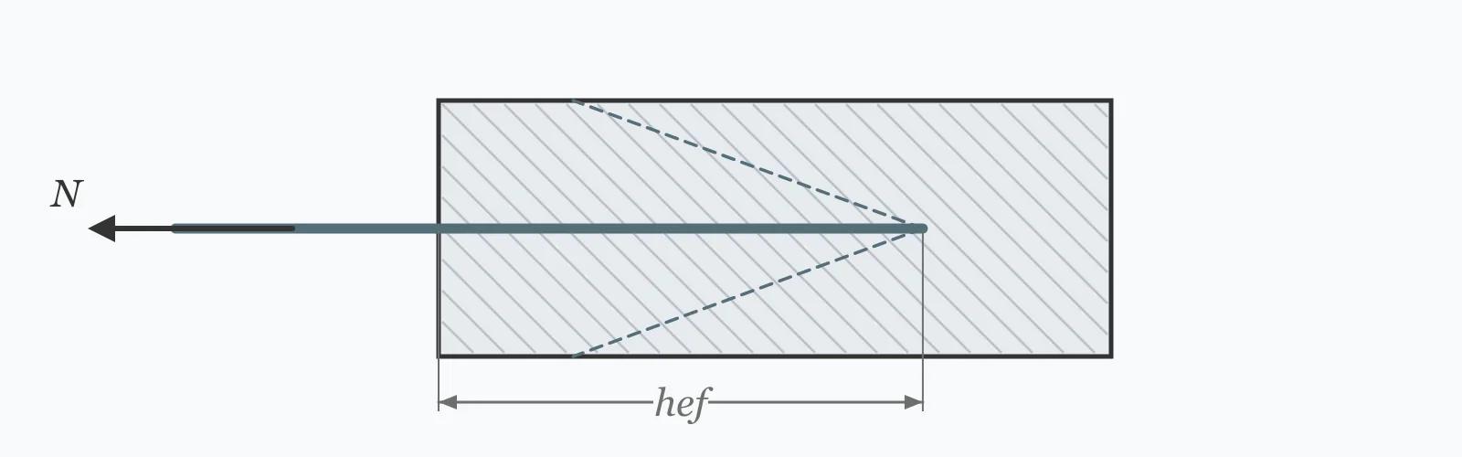
An anchor in tension fails either by pulling a cone of concrete out or by the steel yielding, and only the second gives warning. Enter the embedment depth, concrete strength, anchor diameter, steel strength and edge distance to get both capacities, which one governs, and how much the edge reduces the cone.
Calculator
Units:
mm
Effective embedment of the anchor into the concrete
MPa
Cylinder compressive strength f'c
mm
Nominal diameter of the anchor bar
MPa
640 MPa for grade 8.8; 800 for grade 10.9
mm
Distance to the nearest free edge. Full cone needs 1.5 × embedment
Calculation Result
Press Calculate for the concrete breakout capacity after any edge reduction, the steel capacity of the anchor itself, the governing value, and which of the two failure modes it represents.
Step-by-Step Solution
Preliminary design aid. Results follow the published formulas cited
below and are intended for estimating, study and early design. Final design must be
verified by a licensed Professional Engineer against the code in force for your project.
Key Benefits
✓Compares both failure modes rather than reporting one number
✓Applies the edge distance reduction, which is easy to overlook
✓Identifies whether failure would be brittle or ductile
✓Warns when concrete breakout governs, which codes discourage
✓Sensitivity chart shows the 1.5-power law and where the edge defeats it
✓Shareable links and CSV export for design records
What Is Concrete Anchor Capacity?
A cast-in anchor loaded in tension can fail in several ways, and two dominate. The concrete can break out — a roughly conical wedge of concrete pulls free, radiating outward from the embedded end at about 35 degrees. Or the steel can simply yield and eventually fracture. The ACI concrete capacity design method gives the breakout as Nb = 10·√f'c·hef^1.5, and the steel capacity is the bar area times its strength.
Why the exponent is 1.5
The breakout cone's projected area grows with the square of embedment, but the tensile stress it can develop falls as depth increases, because the concrete's tensile behaviour is size-dependent. The net result is an exponent of 1.5 rather than 2 — capacity still grows faster than depth, but not as fast as the geometry alone would give. It remains the most effective lever available: doubling the embedment multiplies the breakout capacity by 2.83.
What the edge does to the cone
The cone needs room to form. Full capacity requires an edge distance of at least 1.5 times the embedment; closer than that, part of the cone is missing and the capacity falls in proportion to what remains. This has an awkward consequence — near an edge, deeper embedment increases the required clearance faster than it increases capacity, so the 1.5-power law progressively stops paying.
Formula
N_b = 10 · √f'c · hef^1.5
Basic concrete breakout capacity in newtons, with f'c in MPa and hef in mm
Related Formulas
ψ_ed = c / (1.5·hef) where c < 1.5·hef
N_sa = A_se · f_uta
N_governing = min(N_breakout, N_steel)
Variable Definitions
Symbol
Variable
Unit
Description
hef
Embedment Depth
mm
Effective embedment. Breakout grows with its 1.5 power.
f'c
Concrete Strength
MPa
Cylinder compressive strength. Breakout grows with its square root only.
d
Anchor Diameter
mm
Nominal bar diameter, setting the steel area.
f_uta
Steel Strength
MPa
Tensile strength of the anchor steel. 640 MPa for grade 8.8.
c
Edge Distance
mm
Distance to the nearest free edge. Full capacity needs 1.5·hef.
N
Capacity
kN
Tension the anchor can carry, governed by the lower of the two modes.
How to Use This Calculator
Use the effective embedmentThat is the depth of concrete engaged by the anchor, measured from the surface to the bearing element — the head of a cast-in bolt or the end of a bonded bar. It is not the total bolt length, and for some anchor types the manufacturer defines it specifically.
Check the edge distance against 1.5 times the embedmentFull breakout capacity needs that clearance for the cone to form. Closer than it, the capacity falls in proportion to the truncated cone, and this calculator applies the reduction automatically.
Aim for steel to governSteel yielding is ductile and visible; concrete breakout is brittle and sudden. Where breakout governs, increasing the embedment is the direct remedy — but check that the edge distance can grow with it, or the gain will be lost to truncation.
Use the tensile strength, not the yieldAnchor steel capacity is normally based on the ultimate tensile strength rather than yield. For grade 8.8 that is 800 MPa nominal, though design values are lower — take the figure from the applicable code rather than the bolt marking.
Treat this as two modes of severalA full check to ACI 318 Chapter 17 also covers pullout, side-face blowout, shear, combined tension and shear, and group effects where anchors are close enough that their cones overlap. Cracked concrete reduces breakout by around 30% as well.
Worked Examples
Example 1
An M16 cast-in anchor of grade 8.8 steel, embedded 125 mm in 30 MPa concrete, 200 mm from the nearest edge.
The actual edge distance of 200 mm exceeds it, so the full cone develops and no reduction applies
Steel area: π × 16²/4 = 201.1 mm²
Steel capacity: 201.1 × 640/1000 = 128.68 kN
Concrete breakout at 76.55 kN is lower than steel at 128.68 kN, so breakout governs
Interpretation: this anchor would fail brittly, by a cone of concrete lifting out. Codes prefer the reverse, and here that would need considerably deeper embedment — with a correspondingly larger edge distance to let the bigger cone form.
Example 2
The same anchor at increasing embedment with the 200 mm edge distance held fixed — where the 1.5-power law stops paying.
Step-by-Step Solution
At 75 mm: critical edge 112.5 mm, full cone, breakout 35.58 kN
At 125 mm: critical edge 187.5 mm, full cone, breakout 76.55 kN
At 150 mm: critical edge 225 mm exceeds the 200 mm available, so the cone is truncated to 89% — breakout 89.44 kN
At 200 mm: critical edge 300 mm, cone truncated to 67% — breakout 103.28 kN
At 250 mm: critical edge 375 mm, cone truncated to 53% — breakout 115.47 kN
From 75 to 125 mm the capacity rose by a factor of 2.15, close to the 2.15 the pure 1.5-power law predicts. From 125 to 250 mm — the same doubling — it rose by only 1.51.
Beyond about 133 mm the critical edge distance exceeds the 200 mm available, and every further millimetre of embedment demands 1.5 mm more clearance than exists. Deeper embedment then buys capacity at a steadily worsening rate.
Steel would only govern above 310 mm embedment at this edge distance, against 176 mm if the edge were unrestricted. The edge distance, not the embedment, is what prevents a ductile design here.
Embedment Sensitivity
Breakout capacity rises with the 1.5 power of embedment until the edge distance starts truncating the cone, after which the curve flattens markedly. The steel capacity is a horizontal line — where the two cross is where the failure mode changes. The marker shows your current embedment.
Concrete Breakout vs Embedment Depth
Recomputed live from your inputs. The marker shows your current value.
Line chart of Concrete Breakout against Embedment Depth. The same
values are listed in the data table below.
Values plotted above, sampled across the embedment depth range.
How to Interpret Your Results
The governing capacity is the design value, but which mode governs matters as much as the number. A brittle mode gives no warning and no reserve past the peak.
The concrete cone fails before the steel yields. This is a sudden failure with no visible warning and no capacity beyond the peak. Codes prefer steel-governed anchors; deeper embedment is the direct remedy, provided the edge distance can grow with it.
The anchor steel yields before the concrete breaks out, which is the preferred arrangement. The anchor stretches visibly and holds load past yield, giving warning and some redistribution before failure.
Governing Capacity: < 20Low capacity
A capacity of your result kN is modest. Check whether the embedment is unnecessarily shallow — capacity grows with the 1.5 power of embedment, so it is usually the most effective variable available.
A capacity of your result kN is in the normal range for a single structural anchor. Where several anchors sit close together their cones overlap and the group capacity is less than the sum of the individuals.
Concrete Breakout: ≥ 200High breakout capacity
A breakout capacity of your result kN indicates deep embedment or strong concrete. Verify the pullout and side-face blowout modes as well, which can govern at deep embedment where breakout does not.
Common Mistakes to Avoid
Reporting capacity without identifying the mode
Why it matters:A brittle concrete failure and a ductile steel failure at the same number are not equivalent designs. Breakout gives no warning; steel stretches visibly and holds load past yield.
✓How to avoid it:Check both modes and prefer steel to govern. Where breakout governs, either deepen the embedment or accept that a higher factor of safety is warranted for a brittle mode.
Ignoring the edge distance
Why it matters:The breakout cone needs 1.5 times the embedment to form fully. At 200 mm from an edge with 250 mm embedment, only 53% of the cone exists and the capacity falls accordingly — a reduction of nearly half that a basic formula would miss.
✓How to avoid it:Always check c against 1.5·hef. Two nearby edges reduce it further, and a corner position more still.
Increasing embedment near an edge and expecting the 1.5-power gain
Why it matters:Deeper embedment increases the required edge clearance in proportion to it. Past the point where 1.5·hef exceeds the available edge distance, every millimetre deeper demands 1.5 mm more clearance that is not there.
✓How to avoid it:Move the anchor away from the edge, or accept the diminishing return. In the worked example, doubling embedment from 125 to 250 mm gained only 51% instead of the 183% the power law would give.
Assuming higher concrete strength helps much
Why it matters:Breakout grows with the square root of f'c, so going from 30 to 50 MPa concrete — a 67% increase — raises the capacity by only 29%. Embedment, at the 1.5 power, is far more effective.
✓How to avoid it:Increase the embedment rather than the concrete grade when breakout governs. The concrete strength is usually fixed by other considerations anyway.
Overlooking group effects
Why it matters:Anchors closer together than three times their embedment have overlapping cones, so the group capacity is less than the sum of the individual anchors. The overlap can be substantial in a tight bolt pattern.
✓How to avoid it:Compute the projected area of the group cone rather than summing individuals. ACI 318 Chapter 17 sets out the geometry.
Using uncracked concrete capacity in a cracked region
Why it matters:Concrete in tension zones cracks under service load, and a crack through the anchor's cone reduces the breakout capacity by around 30%. Most structural concrete in flexure is cracked at the tension face.
✓How to avoid it:Assume cracked concrete unless it can be shown the anchor sits in a permanently compressed zone. The uncracked assumption needs justifying, not the cracked one.
Practical Applications
▸Checking cast-in anchor capacity in tension
▸Comparing embedment depths for a required capacity
▸Assessing the effect of edge distance on an anchor
▸Verifying that a design fails in a ductile mode
▸Screening baseplate and equipment fixings
▸Reviewing an existing anchorage against a new load
Industry Use Cases
Structural steelwork
Column baseplates use cast-in holding-down bolts, and edge distance is often constrained by the pedestal size. Where the pedestal cannot grow, deeper embedment stops paying and additional bolts or a larger pedestal become the only routes to more capacity.
Equipment and plant fixing
Machine bases fixed to slabs frequently sit near slab edges or joints, both of which truncate the breakout cone. A fixing designed on the basic formula and installed near an edge can have barely half its assumed capacity.
Retrofit and strengthening
Post-installed anchors into existing concrete carry the additional uncertainty of an unknown crack state. Since cracked concrete reduces breakout by around 30%, the cracked assumption is the defensible one unless the location is demonstrably in compression.
Expert Tips
💡Breakout goes with hef^1.5 — doubling embedment multiplies it by 2.83.
💡Concrete strength enters only as a square root, so grade is a weak lever.
💡Full cone capacity needs an edge distance of 1.5 × embedment.
💡Steel governing is ductile; concrete breakout is brittle and sudden.
💡Cracked concrete reduces breakout capacity by around 30%.
💡Anchors closer than 3·hef have overlapping cones and share capacity.
Advantages & Limitations
Advantages
✓Compares both principal failure modes rather than giving one number
✓Applies the edge reduction automatically
✓States whether the governing mode is ductile or brittle
✓Makes visible where the edge distance defeats the embedment law
✓Fast enough to test embedment and edge combinations during design
Limitations
!Tension only — shear and combined tension-shear need separate checks
!Covers breakout and steel; pullout and side-face blowout are not included
!Assumes a single anchor with no group overlap
!Assumes uncracked concrete; cracked reduces breakout by around 30%
!Applies one edge distance; corners and second edges reduce capacity further
!Uses the cast-in coefficient; post-installed anchors have their own qualified values
!Gives nominal capacity without code strength reduction factors
Where the Edge Distance Defeats the Embedment
An M16 grade 8.8 anchor in 30 MPa concrete with the edge distance fixed at 200 mm. The 1.5-power law holds only while the cone has room to form.
M16, f'c = 30 MPa, edge distance 200 mm throughout. Below 133 mm embedment the cone forms fully and capacity follows hef^1.5 — 75 to 125 mm gives a factor of 2.15. Above it the cone is truncated, and the same doubling from 125 to 250 mm gives only 1.51. Steel would govern above 310 mm here, against 176 mm with an unrestricted edge.
Compute the concrete breakout as Nb = 10·√f'c·hef^1.5, apply any edge reduction, and compare it against the steel capacity of the anchor. The lower value governs.
Why is concrete breakout a brittle failure?
A cone of concrete lifts out suddenly with no visible warning, and nothing carries load afterwards. Steel yielding stretches visibly first and holds load past yield, which is why codes prefer it to govern.
What edge distance does an anchor need?
At least 1.5 times the embedment depth for the full breakout cone to form. Closer than that, the capacity falls in proportion to the part of the cone that still exists.
How much does deeper embedment help?
Capacity grows with hef^1.5, so doubling the embedment multiplies it by 2.83 — provided the edge distance grows with it. Near a fixed edge, the gain is progressively lost to cone truncation.
Does stronger concrete increase anchor capacity?
Only weakly. Breakout grows with the square root of f'c, so going from 30 to 50 MPa raises it by 29% for a 67% increase in grade. Embedment is a far more effective variable.
What is the difference between cracked and uncracked concrete?
A crack through the breakout cone reduces its capacity by around 30%. Most structural concrete in flexure is cracked at the tension face, so the cracked assumption is the defensible default.
How do anchors in a group interact?
Anchors closer than about three times their embedment have overlapping cones, so the group carries less than the sum of the individuals. The group capacity is computed from the combined projected area rather than by addition.
Should I use yield or tensile strength for the steel?
Tensile strength, typically. Anchor steel capacity is based on the ultimate rather than the yield, though design values include reduction factors — take the figure from the applicable code rather than the bolt marking.
What other failure modes should I check?
Pullout, side-face blowout, shear, and combined tension and shear. Deep anchors near an edge are particularly susceptible to side-face blowout, which breakout alone would not reveal.
How do I make an anchor fail in a ductile mode?
Increase the embedment until the breakout capacity exceeds the steel capacity — 176 mm for the M16 example with an unrestricted edge. Near an edge that threshold rises sharply, to 310 mm at a 200 mm edge distance.
Glossary
Concrete breakout
Failure by a cone of concrete pulling free around the embedded anchor.
Effective embedment
The depth of concrete engaged by the anchor, from the surface to its bearing element.
CCD method
The concrete capacity design approach underlying ACI 318 Chapter 17.
Edge distance
Distance from the anchor to the nearest free edge, limiting the cone.
Ductile failure
Failure preceded by visible yielding, retaining load-carrying capacity.
Brittle failure
Sudden failure with no warning and no reserve past the peak.
Pullout
Failure by the anchor head crushing through the concrete without a full cone.
Side-face blowout
Lateral concrete failure at a deep anchor close to an edge.
Group effect
Reduction in capacity where adjacent anchors have overlapping breakout cones.
Cracked concrete
Concrete in a tension zone with flexural cracks, reducing anchor capacity by around 30%.
Scientific & Standards References
ACI 318 — Building Code Requirements for Structural Concrete, Chapter 17: Anchoring to Concrete — American Concrete Institute
Fuchs, W., Eligehausen, R. and Breen, J. E., Concrete Capacity Design (CCD) Approach for Fastening to Concrete, ACI Structural Journal (1995) — American Concrete Institute
EN 1992-4 (Eurocode 2 Part 4) — Design of fastenings for use in concrete — CEN
Eligehausen, R., Mallée, R. and Silva, J. F., Anchorage in Concrete Construction — Ernst & Sohn
EOTA TR 049 — Post-installed fasteners in concrete under seismic action — European Organisation for Technical Assessment
Conclusion
An anchor's capacity is the lower of two numbers, and which one it is matters as much as the value. Concrete breakout is brittle — a cone lifts out without warning — while steel yielding stretches visibly and holds load past yield, which is why codes prefer it to govern. Breakout grows with the 1.5 power of embedment, making depth by far the most effective variable: concrete strength enters only as a square root, so a 67% increase in grade buys 29% more capacity. The complication is the edge. A full cone needs 1.5 times the embedment in clearance, and once that exceeds what is available, every further millimetre of depth demands more room than exists. The table above shows the consequence: 75 to 125 mm gained a factor of 2.15 as the power law predicts, while the same doubling from 125 to 250 mm gained only 1.51. Where breakout governs and the edge is fixed, more anchors or a larger pedestal usually beat a deeper hole.
Enter your embedment, concrete grade and edge distance above to see which mode governs.