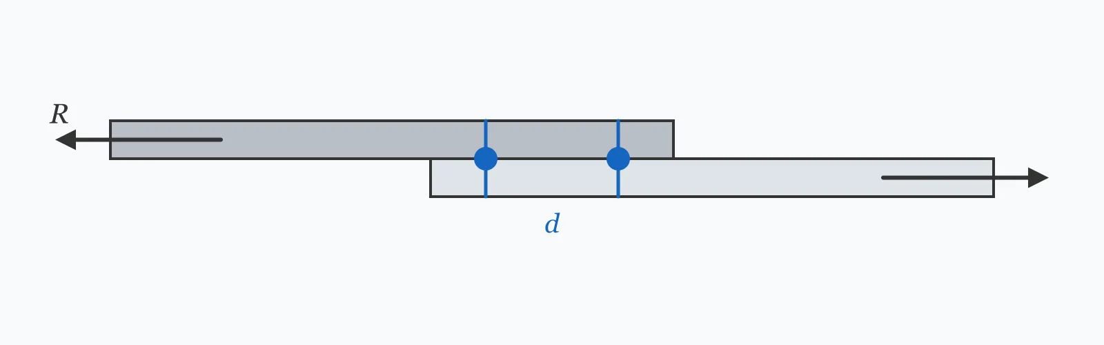
A bolt in shear carries Rn = Fnv·Ab, where Ab is the gross bolt area and Fnv the nominal shear stress from AISC 360 Table J3.2. Enter the bolt diameter and Fnv to get the area and nominal capacity per shear plane. Apply ϕ = 0.75 for LRFD, multiply by the number of shear planes, and check bearing and tear-out separately.
Calculator
Units:
mm
Nominal shank diameter — M16, M20, M24 are the common sizes
Press Calculate for the gross bolt area and the nominal shear capacity of one bolt in one shear plane. This is the nominal value: multiply by ϕ = 0.75 for LRFD design capacity, and by the number of shear planes for a double-shear joint.
Step-by-Step Solution
Preliminary design aid. Results follow the published formulas cited
below and are intended for estimating, study and early design. Final design must be
verified by a licensed Professional Engineer against the code in force for your project.
Key Benefits
✓Applies AISC 360 §J3.6 exactly, using gross area as the specification requires
✓Includes the full Fnv table for Group A and Group B bolts, threads included or excluded
✓Makes the ϕ = 0.75 resistance factor explicit rather than burying it
✓Sets out the bearing, tear-out and block shear checks that must accompany it
✓Sensitivity chart shows how capacity grows with the square of bolt diameter
✓Shareable links and CSV export for connection calculation records
What Is Bolt Shear Capacity?
Bolt shear is the failure mode in which a bolt is cut across its shank by plates sliding past one another. AISC 360 §J3.6 gives the nominal strength as Rn = Fnv·Ab, where Ab is the gross cross-sectional area based on the nominal diameter, and Fnv is a nominal shear stress tabulated in Table J3.2. The use of gross area is deliberate: the reduction for the threaded portion is already built into the tabulated Fnv values rather than applied to the area.
Threads included or excluded
Whether the threads fall in the shear plane changes capacity by about a quarter. For Group A bolts such as A325, Fnv is 372 MPa with threads in the shear plane and 469 MPa with them excluded; for Group B such as A490 the values are 469 and 579 MPa. Excluding the threads requires the plies to be thick enough that the unthreaded shank spans the interface — a detail worth confirming on the drawing rather than assuming, since the shorter grip lengths common in thin plate work rarely achieve it.
The three checks this one does not replace
Bolt shear is one of four failure modes in a bearing-type joint. The bolt can shear, the plate can crush in bearing against the bolt, the material between the bolt and a free edge can tear out, and a whole block of material can separate in block shear. Bearing and tear-out are covered by AISC §J3.10 and depend on plate thickness, edge distance and hole spacing — in thin plates they frequently govern well before the bolt does.
Formula
R_n = F_nv · A_b
Nominal shear strength of one bolt in one shear plane, AISC 360 §J3.6
Related Formulas
A_b = πD² / 4
ϕR_n = 0.75 · F_nv · A_b
R_total = n_bolts · n_planes · ϕR_n
R_n = 1.2 L_c t F_u ≤ 2.4 d t F_u
Variable Definitions
Symbol
Variable
Unit
Description
R_n
Nominal Shear Capacity
kN
Shear strength of one bolt in one shear plane, before the resistance factor.
F_nv
Nominal Shear Stress
MPa
Tabulated stress from AISC Table J3.2, already accounting for the threaded area.
A_b
Gross Bolt Area
mm²
Area from the nominal shank diameter, πD²/4. The specification requires gross, not net, area.
D
Nominal Bolt Diameter
mm
Shank diameter of the bolt, e.g. 20 mm for an M20.
ϕ
Resistance Factor
—
0.75 for bolt shear in LRFD. The corresponding ASD safety factor is Ω = 2.00.
n_planes
Shear Planes
—
1 for single shear, 2 for double shear. Capacity scales directly with this number.
How to Use This Calculator
Enter the nominal bolt diameterUse the shank diameter — 20 mm for an M20, 22.2 mm for a 7/8 inch bolt. Do not use the hole diameter or a tensile stress area; AISC requires the gross area for shear.
Select Fnv for the grade and thread conditionTake the value from the table below. If you cannot confirm that the unthreaded shank spans every shear plane, use the threads-included value — it is the conservative and usual assumption.
Apply the resistance factorThe calculator returns nominal capacity. For LRFD, multiply by ϕ = 0.75 to obtain the design strength compared against the factored load. For ASD, divide by Ω = 2.00.
Multiply by shear planes and bolt countA bolt in double shear resists twice this value. For a concentrically loaded group, total capacity is the number of bolts times the planes per bolt times the design capacity of one plane.
Then check bearing, tear-out and block shearCompute the plate bearing and tear-out capacity from AISC §J3.10 and check block shear per §J4.3. In thin plates or with short edge distances, one of these usually governs before the bolt shear does.
Worked Examples
Example 1
An M20 Group A bolt (A325) is used in a bearing-type connection with the threads included in the shear plane, giving Fnv = 372 MPa. Find the nominal and design shear capacity in single shear.
In double shear the same bolt gives 2 × 87.65 = 175.30 kN
Remember this is the bolt check only — bearing on the connected plies must be verified separately and frequently governs.
Example 2
The same M20 bolt, but detailed so the threads are excluded from the shear plane (Fnv = 469 MPa), then compared against the bearing capacity of a 10 mm plate in S355 steel with a 40 mm edge distance. This shows why the bolt is often not the weak link.
Step-by-Step Solution
Bolt shear with threads excluded: Rn = 469 × 314.16 = 147,341 N = 147.34 kN
Design bolt shear: ϕRn = 0.75 × 147.34 = 110.51 kN — a 26% gain over the threads-included case
Now the plate. Clear distance to the edge: Lc = 40 − 22/2 = 29 mm for a 22 mm hole
Tear-out: Rn = 1.2 × Lc × t × Fu = 1.2 × 29 × 10 × 490 = 170,520 N = 170.52 kN
Bearing limit: Rn = 2.4 × d × t × Fu = 2.4 × 20 × 10 × 490 = 235,200 N = 235.20 kN
Governing plate value is the lesser: 170.52 kN nominal, so ϕRn = 0.75 × 170.52 = 127.89 kN
Comparison: bolt shear at 110.51 kN governs over plate bearing at 127.89 kN — but only just. Reduce the plate to 8 mm and bearing drops to 102.3 kN and takes over, which is why both checks are mandatory.
Diameter Sensitivity
Capacity grows with the square of diameter, so an M24 carries 44% more than an M20 despite being only 20% larger. Sweep the diameter to compare standard bolt sizes at your chosen Fnv. The marker shows your current diameter.
Nominal Shear Capacity vs Bolt Diameter
Recomputed live from your inputs. The marker shows your current value.
Line chart of Nominal Shear Capacity against Bolt Diameter. The same
values are listed in the data table below.
Values plotted above, sampled across the bolt diameter range.
How to Interpret Your Results
Nominal capacity is only meaningful once the resistance factor and the number of shear planes are applied. The bands below relate the computed per-plane nominal value to the bolt sizes it corresponds to in ordinary steelwork.
Nominal Shear Capacity: < 60Light connection bolt
A nominal capacity of your result kN per shear plane corresponds to a small bolt used in secondary framing, bracing cleats and light connections. Design capacity is 0.75 × this value, so confirm the bolt count carefully — plate bearing very often governs at this size.
Nominal Shear Capacity: 60 – 200Standard structural bolt range
A nominal capacity of your result kN per shear plane is the normal range for M16 to M24 bolts in building steelwork. Apply ϕ = 0.75, multiply by shear planes and bolt count, and verify bearing and tear-out on the connected plies.
A nominal capacity of your result kN per shear plane indicates a large-diameter or high-grade bolt used in heavy moment connections and splices. At this level the connected plate almost always governs, so check bearing, tear-out and block shear before relying on the bolt value.
Common Mistakes to Avoid
Using the tensile stress area instead of the gross area
Why it matters:AISC deliberately pairs the tabulated Fnv values with gross area; the reduction for threads is already inside Fnv. Substituting the tensile stress area applies the reduction twice and understates capacity by roughly 25%.
✓How to avoid it:Use Ab = πD²/4 from the nominal diameter, exactly as this calculator does. Reserve the tensile stress area for tension checks that call for it explicitly.
Claiming threads excluded without checking the grip
Why it matters:The 26% gain from excluding threads is only real if the unthreaded shank actually spans every shear plane. With thin plies or long thread runs it often does not, and the connection is then weaker than calculated.
✓How to avoid it:Confirm the shank length against the ply thicknesses, or design on the threads-included value. Where it matters, note the requirement explicitly on the drawing.
Reporting nominal capacity as design capacity
Why it matters:Nominal strength omits the resistance factor. Using Rn where ϕRn belongs overstates the design capacity by a third, which is enough to turn a failing connection into an apparently passing one.
✓How to avoid it:Multiply by ϕ = 0.75 for LRFD, or divide by Ω = 2.00 for ASD, before comparing against the applied load.
Forgetting to check plate bearing and tear-out
Why it matters:In thin plates, at short edge distances, or with lower-grade material, the plate fails before the bolt. A design that checks only the bolt can be unconservative by a wide margin.
✓How to avoid it:Run the AISC §J3.10 bearing and tear-out checks for every bolt, and the §J4.3 block shear check for the group. Design on whichever mode gives the least capacity.
Counting one shear plane in a double-shear joint
Why it matters:A bolt passing through three plies is cut on two planes and carries twice the single-plane value. Ignoring the second plane halves the calculated capacity and doubles the bolt count needlessly.
✓How to avoid it:Count the interfaces the bolt crosses. Two plies gives one plane, three plies gives two.
Treating a slip-critical connection as bearing-type
Why it matters:Slip-critical joints are designed to transfer load by friction under bolt pretension, and their capacity is governed by the slip resistance, not by bolt shear. The two give quite different answers.
✓How to avoid it:Where slip must be prevented — oversized holes, fatigue loading, reversing loads — design to AISC §J3.8 for slip resistance and check bearing as a secondary limit state.
Practical Applications
▸Sizing bolt groups in beam-to-column shear connections
▸Designing splice plates in beams and columns
▸Checking bracing connections and gusset plates
▸Verifying base plate anchor arrangements loaded in shear
▸Assessing existing connections against increased loading
▸Checking bolted joints in plant, racking and equipment supports
Industry Use Cases
Steel fabrication and detailing
Detailers size shear connections from standardised tables generated by this calculation. When a beam reaction falls outside the tabulated range, the check is run directly to confirm whether an extra bolt row or a thicker cleat is the cheaper answer.
Structural assessment
Older connections often use bolts of unknown grade. Engineers compute capacity across the plausible range of Fnv values, and where even the lowest assumption passes, no material testing is needed — which saves considerable survey cost.
Modular and off-site construction
Volumetric modules are joined on site entirely by bolted connections, so bolt shear governs the erection sequence. Designers size for double shear where possible, since it halves the bolt count and the labour that goes with it.
Expert Tips
💡Capacity scales with the square of diameter: an M24 gives 44% more than an M20 for a 20% size increase.
💡Double shear doubles capacity at no material cost — arrange plies for it whenever the geometry allows.
💡In thin plates, check bearing first. Below about 10 mm it usually governs and the bolt calculation is academic.
💡Standardise on one bolt size per project where possible; the erection saving normally outweighs the steel saving from optimising each joint.
💡Edge distance drives tear-out directly. Increasing it from 1.5d to 2d often buys more capacity than upsizing the bolt.
💡Record the thread condition assumed. It is a 26% difference, and it is invisible on site once the joint is made.
✓Uses gross area, avoiding the most common source of double-counting
✓Scales trivially to bolt groups and multiple shear planes
✓Applies equally to Group A and Group B bolts through the Fnv input
✓Fast enough to compare connection options during scheme design
Limitations
!Covers bolt shear only — bearing, tear-out and block shear are separate checks that often govern
!Returns nominal capacity, so the ϕ = 0.75 factor must be applied by the user
!Gives one shear plane per bolt; double shear must be accounted for separately
!Assumes a bearing-type connection, not a slip-critical one
!Takes no account of combined shear and tension, which requires the interaction equation of §J3.7
!Does not include the length reduction AISC applies to connections longer than 965 mm
!Assumes concentric loading; eccentric bolt groups require an instantaneous-centre or elastic vector analysis
Nominal Shear Stress Fnv by Bolt Grade
Fnv already accounts for the reduced area at the threads, which is why it is paired with the gross bolt area. The threads-excluded values require the unthreaded shank to span every shear plane — a detailing condition, not a default.
Values after AISC 360-22 Table J3.2 for ASTM grades. European figures are indicative — design to EN 1993-1-8, which uses a different formulation.
Multiply the nominal shear stress by the gross bolt area: Rn = Fnv·Ab, with Ab = πD²/4. For an M20 with Fnv = 372 MPa that gives 116.87 kN per shear plane. Apply ϕ = 0.75 for LRFD design capacity.
Why does AISC use gross area rather than the thread area?
Because the reduction for the threaded section is already built into the tabulated Fnv values. Pairing them with gross area keeps the calculation simple; using the tensile stress area as well would apply the same reduction twice and understate capacity by around a quarter.
What is the difference between single and double shear?
Single shear means the bolt is cut on one plane, as when two plates lap. Double shear means two planes, as when a central plate is sandwiched between two others. Double shear gives exactly twice the capacity for the same bolt.
What does 'threads included in the shear plane' mean?
It describes whether the threaded portion of the bolt crosses the interface between plies. Threads included is the conservative and more common case; excluding them raises Fnv by about 26% but requires the unthreaded shank to span every shear plane.
What is Fnv for an A325 bolt?
372 MPa (54 ksi) with threads included in the shear plane, and 469 MPa (68 ksi) with them excluded, per AISC 360 Table J3.2. For A490 the corresponding values are 469 and 579 MPa.
Does bolt shear always govern a connection?
No, and frequently it does not. Plate bearing, tear-out to a free edge and block shear all compete, and in thin plates or with short edge distances one of those governs first. All four modes must be checked and the lowest capacity taken.
What resistance factor applies to bolt shear?
ϕ = 0.75 in LRFD, giving ϕRn = 0.75·Fnv·Ab. In ASD the corresponding safety factor is Ω = 2.00, so the allowable capacity is Rn/2.00. Use one system consistently throughout a connection design.
How does bolt diameter affect capacity?
Capacity is proportional to the square of diameter, since area is. Going from M20 to M24 raises capacity by (24/20)² = 1.44, a 44% gain. Bearing capacity, by contrast, scales linearly with diameter, so the two modes shift relative to each other as bolts get larger.
What is a slip-critical connection?
One in which load is transferred by friction between pretensioned plies rather than by bearing on the bolts. It is required where slip would be unacceptable — oversized holes, fatigue, or load reversal — and is designed to AISC §J3.8, which gives different and usually lower capacities.
How do I handle combined shear and tension in a bolt?
Use the interaction provisions of AISC 360 §J3.7, which reduce the available tensile stress as a function of the applied shear stress. Checking the two independently is unconservative for bolts loaded in both directions at once, as in an end-plate moment connection.
Glossary
Nominal shear stress (Fnv)
The tabulated shear stress for a bolt grade and thread condition, from AISC 360 Table J3.2.
Gross bolt area (Ab)
The area πD²/4 based on the nominal shank diameter, used with Fnv in the AISC shear expression.
Shear plane
An interface between connected plies across which the bolt is cut. One per interface the bolt crosses.
Single shear
A joint in which the bolt crosses one interface and is therefore cut on a single plane.
Double shear
A joint in which the bolt crosses two interfaces, giving twice the shear capacity.
Bearing-type connection
A joint that transfers load by bolts bearing against hole walls, permitting a small amount of slip.
Slip-critical connection
A joint that transfers load by friction between pretensioned plies, designed to prevent slip entirely.
Tear-out
Failure in which the material between a bolt hole and a free edge shears away, governed by clear distance and plate thickness.
Block shear
A failure mode in which a block of material separates along a combination of tension and shear planes through a bolt group.
Edge distance
The distance from a bolt centre to the nearest free edge, which controls tear-out capacity.
Scientific & Standards References
AISC 360-22 §J3.6 — Shear Strength of Bolts and Threaded Parts — American Institute of Steel Construction
AISC 360-22 Table J3.2 — Nominal Stress of Fasteners — American Institute of Steel Construction
AISC 360-22 §J3.10 — Bearing and Tearout Strength at Bolt Holes — American Institute of Steel Construction
AISC 360-22 §J4.3 — Block Shear Strength — American Institute of Steel Construction
RCSC Specification for Structural Joints Using High-Strength Bolts — Research Council on Structural Connections
EN 1993-1-8 §3.6 — Design resistance of individual fasteners — CEN
Conclusion
Bolt shear capacity follows Rn = Fnv·Ab, using the gross bolt area because the thread reduction is already inside the tabulated Fnv. Apply ϕ = 0.75 for LRFD, multiply by the number of shear planes, and remember that the bolt is only one of four failure modes: bearing, tear-out and block shear all depend on plate geometry rather than on the fastener, and in thin plates or at short edge distances one of them will govern first. The thread condition is worth recording explicitly — it is a 26% difference, and it is impossible to verify once the joint is closed.
Check your own bolt above, then sweep the diameter in the chart to compare standard sizes at your chosen grade.