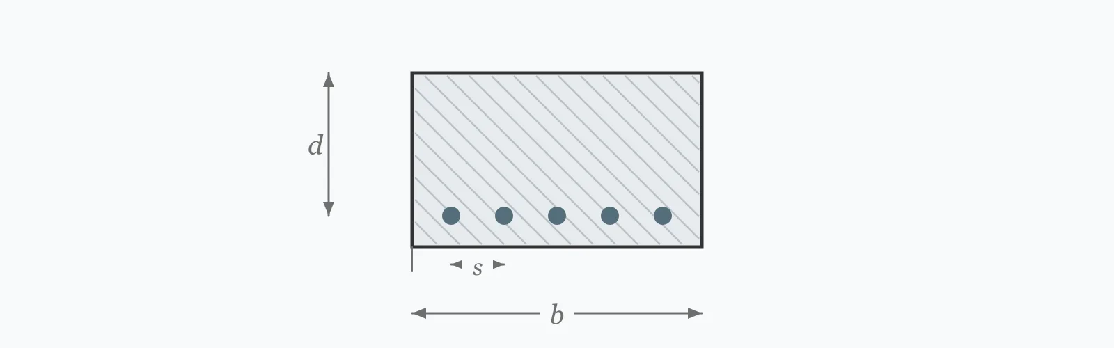
Given a required steel area, the bar spacing follows from the area one bar provides. Enter the bar diameter, the required steel area per metre, and the member dimensions to get the spacing in millimetres and the reinforcement ratio. Spacing is then checked against the code's minimum for placing and maximum for crack control.
Calculator
Units:
mm
8, 10, 12, 16, 20, 25, 32 mm are standard sizes
mm²/m
From the flexural design, per metre width
mm
Use 1000 mm for a slab designed per metre
mm
Compression face to centroid of tension steel
Calculation Result
Press Calculate for the area of one bar, the number of bars needed per metre, the resulting centre-to-centre spacing rounded down to a 5 mm increment, and the reinforcement ratio.
Step-by-Step Solution
Preliminary design aid. Results follow the published formulas cited
below and are intended for estimating, study and early design. Final design must be
verified by a licensed Professional Engineer against the code in force for your project.
Key Benefits
✓Converts a required steel area directly into a buildable bar spacing
✓Rounds spacing down to a 5 mm increment, the way drawings are actually dimensioned
✓Returns the reinforcement ratio for checking against code minima and maxima
✓Warns on spacings too tight to place concrete through
✓Sensitivity chart shows how spacing responds to bar diameter
✓Shareable links and CSV export for detailing records
What Is Rebar Spacing?
A reinforcement schedule specifies a bar size at a spacing — 'H12 at 125 centres' — rather than an area. Converting from the area a design requires is a matter of dividing: one 12 mm bar provides 113.1 mm² of steel, so achieving 900 mm² per metre needs 900/113.1 = 7.96 bars per metre, rounded up to 8, which puts them at 125 mm centres. The rounding always goes up on bar count and therefore down on spacing, since providing less steel than required is not an option.
The reinforcement ratio
Dividing the steel area by the gross concrete area gives the reinforcement ratio ρ, the number that tells you whether a section is sensibly proportioned. Codes impose a minimum — 0.0018 of the gross area for slab shrinkage and temperature steel — to ensure cracking is distributed rather than concentrated. They also impose a practical maximum around 2 to 4% in beams, above which the section becomes congested and the failure mode shifts from ductile to brittle.
Why spacing has limits at both ends
The minimum spacing exists so concrete can actually pass between the bars: ACI requires clear spacing of at least the bar diameter, 25 mm, and four-thirds of the maximum aggregate size. The maximum exists for crack control, since widely spaced bars let cracks open between them; ACI 318 §24.3.2 caps bar spacing in flexural tension zones by a formula that works out near 250 to 300 mm for typical service stresses.
Formula
s = 1000 / (A_s,req / A_bar)
Centre-to-centre spacing to provide the required steel area per metre
Related Formulas
A_bar = π d_b² / 4
ρ = A_s / (b · d)
s_clear ≥ max(d_b, 25 mm, 4/3 · d_agg)
A_s,min = 0.0018 · b · h
Variable Definitions
Symbol
Variable
Unit
Description
s
Bar Spacing
mm
Centre-to-centre distance between adjacent bars, the dimension shown on the drawing.
d_b
Bar Diameter
mm
Nominal diameter of the reinforcing bar. Area grows with its square.
A_s
Required Steel Area
mm²/m
Steel area per metre width, from the flexural design of the section.
A_bar
Area per Bar
mm²
Cross-sectional area of a single bar, πd²/4.
b
Member Width
mm
Width of the section. Use 1000 mm when working per metre of slab.
d
Effective Depth
mm
Distance from the compression face to the centroid of tension steel.
ρ
Reinforcement Ratio
%
Steel area as a percentage of gross concrete area, checked against code limits.
How to Use This Calculator
Take the required area from the flexural designThis calculator arranges steel; it does not size it. The required area comes from the moment capacity check, and for a slab it is expressed per metre of width.
Choose a bar diameter that suits the memberSlabs typically use 10 to 16 mm bars, beams 16 to 32 mm. Smaller bars at closer centres control cracking better for the same area, which is why slab steel is rarely large.
Set the member width to 1000 mm for slabsWorking per metre keeps the arithmetic simple and matches how slab reinforcement is specified. For a beam, enter the actual width and the required area for the whole section.
Check the spacing against both limitsConfirm clear spacing is at least the bar diameter, 25 mm, and four-thirds of the maximum aggregate size. Then confirm it does not exceed the crack-control maximum, typically 250 to 300 mm in flexural tension zones.
Check the reinforcement ratioCompare against the minimum for shrinkage and temperature — 0.18% of gross area for Grade 420 slabs — and the practical maximum of 2 to 4% in beams, above which placing concrete becomes difficult.
Worked Examples
Example 1
A one-way slab requires 900 mm²/m of tension reinforcement. The slab is 250 mm thick with an effective depth of 200 mm. Use 12 mm bars and find the spacing.
Step-by-Step Solution
Area of one bar: A_bar = πd²/4 = π × 12² / 4 = π × 144 / 4 = 113.1 mm²
Bars required per metre: 900 / 113.1 = 7.96, so 8 bars per metre
Spacing: 1000 / 8 = 125 mm centres
Steel provided: 8 × 113.1 = 904.8 mm²/m, just above the 900 mm² required
Check the minimum: shrinkage and temperature steel needs 0.0018 × 1000 × 250 = 450 mm²/m — comfortably exceeded
Check clear spacing: 125 − 12 = 113 mm clear, well above the 25 mm minimum and four-thirds of a 20 mm aggregate
Specify: H12 at 125 mm centres.
Example 2
The same required area, but using 16 mm bars instead of 12 mm to reduce the number of bars to fix. This shows the trade against crack control.
Step-by-Step Solution
Area of one bar: A_bar = π × 16² / 4 = 201.1 mm²
Bars required per metre: 900 / 201.1 = 4.48, so 5 bars per metre
Spacing: 1000 / 5 = 200 mm centres
Steel provided: 5 × 201.1 = 1,005.3 mm²/m — 12% more than required, because rounding up from 4.48 to 5 is a large jump
Comparison: 5 bars to fix instead of 8, a real saving in fixing labour
But the over-provision is 12% against 0.5% for the 12 mm option, so more steel is bought than needed.
And the spacing has opened from 125 to 200 mm. Both are inside the crack-control limit, but wider spacing gives wider individual cracks for the same steel stress — which is why slabs exposed to weather usually keep to smaller bars at closer centres.
Bar Size Sensitivity
Because bar area grows with the square of diameter, spacing opens up quickly as bars get larger — but the steps are coarse, since bar counts are whole numbers. Watch where the spacing crosses the 250 to 300 mm crack-control ceiling. The marker shows your current bar size.
Required Spacing vs Bar Diameter
Recomputed live from your inputs. The marker shows your current value.
Line chart of Required Spacing against Bar Diameter. The same
values are listed in the data table below.
Values plotted above, sampled across the bar diameter range.
How to Interpret Your Results
Two numbers matter here and they are checked against different things: spacing against the placing and crack-control limits, and the reinforcement ratio against the code minimum and the practical maximum.
Required Spacing: < 75Too tight to place concrete
A spacing of your result mm leaves very little clear distance between bars. Concrete and a vibrator must pass through: ACI requires clear spacing of at least the bar diameter, 25 mm, and four-thirds of the maximum aggregate size. Use a larger bar at wider centres.
Required Spacing: 75 – 300Practical spacing range
A spacing of your result mm is buildable and within the usual crack-control limits. Confirm the clear spacing against the maximum aggregate size, and check the crack-control maximum if the member is exposed to weather.
Required Spacing: ≥ 300Wide spacing — crack control at risk
A spacing of your result mm exceeds the crack-control maximum applied to flexural tension zones, roughly 250 to 300 mm at typical service stresses. Cracks between widely spaced bars open wider. Use smaller bars at closer centres for the same steel area.
Reinforcement Ratio (ρ): < 0.18Below the minimum reinforcement ratio
A ratio of your result% falls below the 0.18% minimum ACI applies for shrinkage and temperature steel in Grade 420 slabs. Minimum reinforcement exists to distribute cracking rather than let it concentrate, and applies regardless of what the flexural calculation requires.
Reinforcement Ratio (ρ): ≥ 4Very high reinforcement ratio
A ratio of your result% is above the practical maximum for beams. The section is congested, concrete will be difficult to place around the bars, and the failure mode shifts away from ductile yielding of the steel. Increase the section size instead.
Common Mistakes to Avoid
Rounding the bar count down
Why it matters:Rounding 7.96 bars down to 7 provides 792 mm² against 900 required — 12% short. Steel area must be at least the required value, never approximately it.
✓How to avoid it:Always round the bar count up, which rounds the spacing down. The small over-provision is the price of using whole bars.
Ignoring the maximum spacing limit
Why it matters:Satisfying the steel area with a few large bars at wide centres meets the strength requirement but not the crack-control one. Cracks between widely spaced bars open wider for the same steel stress.
✓How to avoid it:Check the ACI 318 §24.3.2 spacing limit, which works out near 250 to 300 mm at typical service stresses, and tighter where the member is exposed.
Forgetting minimum reinforcement
Why it matters:A lightly loaded slab may need very little steel for strength, but shrinkage and thermal movement still crack it. Minimum reinforcement distributes that cracking into many fine cracks rather than a few wide ones.
✓How to avoid it:Provide at least 0.0018 times the gross area for Grade 420 slabs, and the flexural minimum for beams, regardless of the calculated requirement.
Using the gross depth instead of the effective depth
Why it matters:The reinforcement ratio is defined on the effective depth to the steel centroid, not the overall section depth. Using the gross depth understates the ratio by 15 to 25%.
✓How to avoid it:Effective depth is overall depth minus cover minus half the bar diameter, minus the link diameter where links are present.
Not checking clear spacing against aggregate size
Why it matters:The 25 mm minimum is not the only limit. Four-thirds of the maximum aggregate size can govern — with 20 mm aggregate that is 26.7 mm, and with 40 mm aggregate it is 53 mm.
✓How to avoid it:Check all three minimum criteria and take the largest. Where bars are congested, specifying a smaller maximum aggregate size is a valid response.
Treating spacing as independent of anchorage
Why it matters:Bars need to be developed as well as spaced. Closely spaced bars with minimal cover develop less well, and the ACI simplified development expression assumes clear spacing of at least one bar diameter.
✓How to avoid it:Confirm the spacing satisfies the conditions for the simplified development length, or use the general expression with its confinement term.
Practical Applications
▸Detailing slab reinforcement from a required steel area
▸Setting out beam tension and compression steel
▸Checking wall reinforcement layouts
▸Verifying an existing drawing against a design requirement
▸Comparing bar size options for fixing cost and crack control
▸Confirming minimum shrinkage and temperature reinforcement
Industry Use Cases
Reinforced concrete detailing
Detailers work from bar area tables that list provided area per metre for each size and spacing combination. The calculation runs in reverse when a required area falls between tabulated options, to judge whether the next size down at closer centres is more economical.
Steel fixing and site work
Fixing cost scales with bar count rather than tonnage, so contractors favour fewer larger bars. Designers push the other way for crack control, and the resolution usually lands on the smallest bar that keeps the count manageable.
Water-retaining and exposed structures
Crack width rather than strength governs these designs, so spacing limits are much tighter and bar sizes correspondingly smaller. It is common to see the steel area doubled purely to bring crack widths within the durability requirement.
Expert Tips
💡Bar area grows with the square of diameter: one 16 mm bar replaces nearly two 12 mm bars.
💡Smaller bars at closer centres control cracking better than larger bars at wide centres, for the same area.
💡Round bar count up, never down — under-provision of steel is not a rounding question.
💡Watch the over-provision when rounding: going from 4.48 to 5 bars buys 12% more steel than needed.
💡Check clear spacing against four-thirds of the aggregate size, not just the 25 mm minimum.
💡Standard spacings of 100, 125, 150, 200 and 250 mm are easier to set out and less error-prone on site.
Advantages & Limitations
Advantages
✓Converts a design area directly into a buildable drawing dimension
✓Rounds to a 5 mm increment, matching how spacings are actually specified
✓Returns the reinforcement ratio for immediate code checking
✓Fast enough to compare bar size options during detailing
✓Applies equally to slabs, walls and beams
Limitations
!Arranges reinforcement but does not size it — the required area comes from the flexural design
!Does not check the minimum or maximum spacing limits automatically
!Assumes a single layer of bars; multiple layers change the effective depth
!Takes no account of cover, which must be confirmed separately
!Does not verify development length or lap positions
!Assumes uniform spacing across the width, ignoring edge and opening conditions
!Does not compute crack width, which governs water-retaining and exposed structures
Bar Size Options for 900 mm²/m
The same required steel area achieved with different bar sizes. Larger bars mean fewer to fix but more over-provision from rounding, and wider spacing that controls cracking less well.
Options for 900 mm²/m. The 20 and 25 mm spacings exceed the crack-control maximum and would not normally be acceptable in a flexural tension zone.
Divide the required steel area per metre by the area of one bar to get the bars needed, round up to a whole number, then divide 1000 by that count. For 900 mm²/m using 12 mm bars: 900/113.1 = 7.96, round to 8, giving 125 mm centres.
What is the area of a 12 mm rebar?
113.1 mm², from πd²/4. For reference: 10 mm gives 78.5 mm², 16 mm gives 201.1 mm², 20 mm gives 314.2 mm² and 25 mm gives 490.9 mm². Area grows with the square of diameter.
What is the minimum spacing between rebars?
Clear spacing must be at least the bar diameter, 25 mm, and four-thirds of the maximum aggregate size — whichever is largest. The limit exists so concrete and a vibrator can pass between the bars.
What is the maximum rebar spacing?
For crack control in flexural tension zones, ACI 318 §24.3.2 gives a formula that works out near 250 to 300 mm at typical service stresses. Slabs also have a limit of three times the thickness or 450 mm, whichever is less.
What is a typical reinforcement ratio?
Slabs commonly run 0.3 to 0.8%, beams 0.8 to 2%. The minimum for shrinkage and temperature steel is 0.18% of gross area for Grade 420. Above about 2 to 4% in beams, the section becomes congested and behaviour shifts towards brittle.
Should I use fewer large bars or more small ones?
Small bars at close centres control cracking better for the same steel area, and waste less through rounding. Large bars cost less to fix. Slabs generally favour smaller bars; beams, where crack control is less critical and congestion matters more, favour larger.
What is minimum reinforcement for and why does it apply anyway?
It distributes shrinkage and thermal cracking into many fine cracks rather than a few wide ones. Because those effects occur regardless of load, the minimum applies even where the flexural calculation requires almost nothing.
How do I find the effective depth?
Overall depth minus the cover, minus the link diameter where links are present, minus half the main bar diameter. For a 250 mm slab with 30 mm cover and 12 mm bars: 250 − 30 − 6 = 214 mm.
Why is spacing rounded down rather than up?
Because the bar count is rounded up. Providing 7 bars where 7.96 are needed leaves the section 12% short of steel, which is a strength deficiency rather than a rounding nicety. The small over-provision from rounding up is the acceptable direction.
Does bar spacing affect crack width?
Yes, directly. For the same steel area and stress, widely spaced bars produce fewer but wider cracks, while closely spaced bars distribute the same total movement into more, finer cracks. This is why exposed and water-retaining structures use small bars at close centres.
Glossary
Bar spacing
The centre-to-centre distance between adjacent reinforcing bars, as specified on a drawing.
Clear spacing
The gap between the surfaces of adjacent bars, equal to the centre spacing minus one bar diameter.
Reinforcement ratio (ρ)
Steel area divided by gross concrete area, used to check a section against code minima and maxima.
Effective depth (d)
Distance from the extreme compression fibre to the centroid of the tension reinforcement.
Shrinkage and temperature reinforcement
Minimum steel provided to distribute cracking from restrained volume change, independent of load.
Cover
The distance from the concrete surface to the nearest bar, protecting the steel from corrosion and fire.
Crack control
Limiting crack widths by distributing reinforcement, achieved through maximum spacing rules rather than strength.
Congestion
A condition where bars are too closely spaced for concrete to be placed and compacted around them.
Over-provision
The excess steel supplied when a fractional bar count is rounded up to a whole number.
Scientific & Standards References
ACI 318-19 §25.2 — Minimum Spacing of Reinforcement — American Concrete Institute
ACI 318-19 §24.3 — Distribution of Flexural Reinforcement in Beams and One-Way Slabs — American Concrete Institute
ACI 318-19 §24.4 — Shrinkage and Temperature Reinforcement — American Concrete Institute
ACI 315 — Details and Detailing of Concrete Reinforcement — American Concrete Institute
EN 1992-1-1 §8.2 and §9.3 — Spacing of bars and slab detailing — CEN
Conclusion
Converting a required steel area into a bar spacing is division followed by rounding up, and the rounding always goes in one direction: more bars, closer centres, because under-providing steel is a strength deficiency rather than a tolerance. What the arithmetic does not tell you is whether the answer is acceptable, and that requires two further checks running in opposite directions. Spacing must be wide enough for concrete and a vibrator to pass between the bars, and close enough that cracks between them stay fine — typically 250 to 300 mm in a flexural tension zone. Where both cannot be satisfied, the answer is a smaller bar at closer centres, not a larger one further apart.
Work out your own layout above, then sweep the bar diameter in the chart to compare the options.