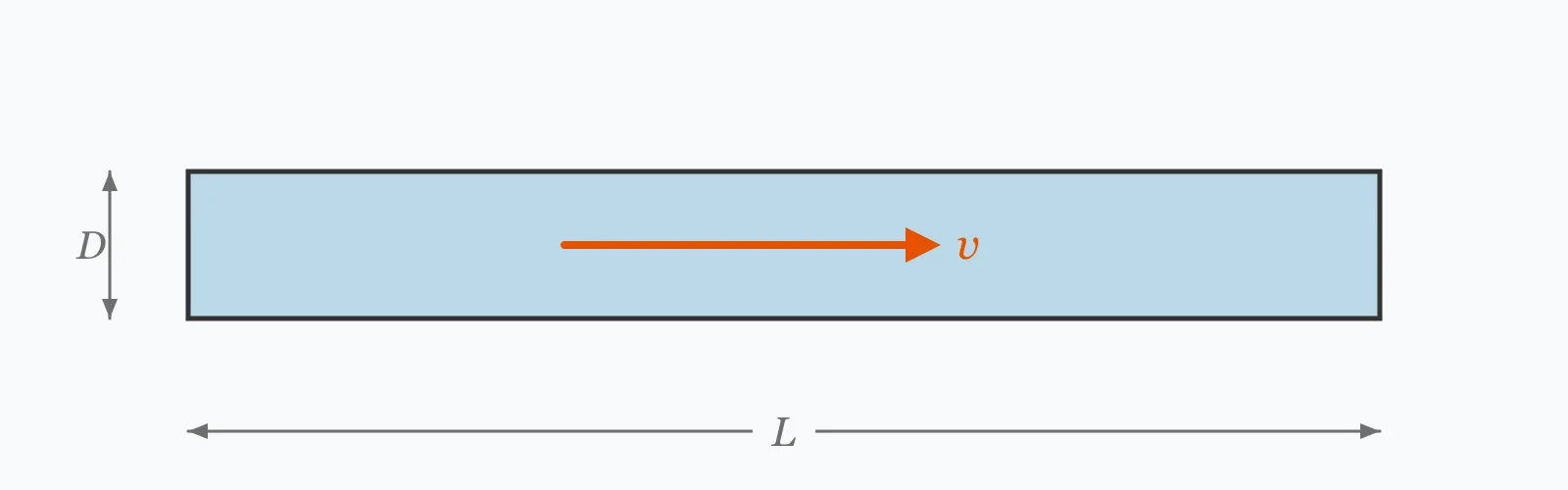
Duct size follows from one division — area equals flow divided by velocity — but the velocity chosen decides everything else. Enter the airflow, target velocity, aspect ratio and run length to get the required area, the round diameter, the rectangular equivalent and the friction pressure drop per metre and over the whole run.
Calculator
Units:
L/s
Volume flow the duct must carry
m/s
Main ducts 5–8, branches 3–5, near occupied spaces below 3
1 is square. Higher means flatter, which fits ceiling voids better
m
Straight run length for the total pressure drop
Calculation Result
Press Calculate for the required cross-sectional area, the equivalent round diameter, and the friction pressure drop per metre and over the run. Straight-duct friction is typically only half the total system resistance.
Step-by-Step Solution
Preliminary design aid. Results follow the published formulas cited
below and are intended for estimating, study and early design. Final design must be
verified by a licensed Professional Engineer against the code in force for your project.
Key Benefits
✓Sizes from airflow and velocity, the way ductwork is actually specified
✓Gives both round and rectangular equivalents
✓Computes friction properly rather than reading a fixed rate
✓Warns on the velocity limits that govern noise and energy
✓Sensitivity chart shows pressure drop climbing far faster than velocity
✓Shareable links and CSV export for design records
What Is HVAC Duct Sizing?
Duct sizing starts from continuity: the cross-sectional area required is the volume flow divided by the velocity chosen. Everything after that follows. A larger duct at a lower velocity costs more in sheet metal, insulation and space but far less in fan energy and noise; a smaller one inverts that. There is no single right answer, only a position on a trade-off that depends on how long the system runs and how much room the building can spare.
Why pressure drop rises so much faster than velocity
Friction pressure drop per metre goes as ρv²/2 divided by the diameter, and for a fixed flow the diameter itself falls as the square root of velocity. Combining the two gives a drop rising roughly with v^2.5. Measured across the range here, going from 3 to 8 m/s — a factor of 2.67 in velocity — multiplies the friction rate by 11.2. Fan power tracks that closely, which is why velocity selection dominates the running cost of a ventilation system.
Round against rectangular
A circle encloses the most area for the least perimeter, so a round duct always has less friction and less material than a rectangular one of the same capacity. Rectangular ducts exist because buildings have flat ceilings and limited depth. The friction penalty is smaller than it looks — a 4:1 flat duct costs only 7% more pressure drop than a square one here — but the extra surface area means more sheet metal, more insulation and more heat gain along the way.
Formula
A = Q / v
Cross-sectional area from volume flow and chosen velocity
Related Formulas
D = √(4A/π)
D_e = 1.30·(a·b)^0.625 / (a+b)^0.25
Δp/L = (f/D)·(ρv²/2)
Variable Definitions
Symbol
Variable
Unit
Description
Q
Airflow
L/s
Volume flow the duct must carry.
v
Velocity
m/s
Chosen air velocity. The single decision that drives noise and energy.
A
Cross-Sectional Area
m²
Flow divided by velocity.
D
Round Diameter
mm
Equivalent circular duct size.
AR
Aspect Ratio
—
Width divided by height for a rectangular duct.
Δp/L
Friction Rate
Pa/m
Pressure drop per metre of straight duct. 0.8 to 1.0 is a common target.
How to Use This Calculator
Choose the velocity from the duct's positionMain plant-room ducts commonly run at 5 to 8 m/s, distribution branches at 3 to 5, and final runs into occupied spaces below 3 to keep noise down. The closer to people, the slower — regenerated noise at a fitting rises steeply with velocity.
Use the round size where you canA circle gives the least friction and the least material for a given area, and spirally wound duct is cheaper to make and to seal. Rectangular sections exist to fit ceiling voids, not because they perform better.
Keep the aspect ratio modestFlatter ducts fit tighter voids but need more sheet metal and more insulation for the same capacity. The friction penalty is modest — 7% from square to 4:1 here — but the material and heat gain penalties are not.
Target a friction rate, not just a velocityMany designers size the whole system to a constant Pa per metre — commonly 0.8 to 1.0 — which balances the network automatically and keeps velocities sensible without checking each one. The default case here lands at 0.835 Pa/m.
Double the straight-duct figure for fittingsBends, transitions, dampers and terminals typically contribute as much again as the straight run, and more on a compact system. Size the fan on the total resistance, not on the friction this calculator gives.
Worked Examples
Example 1
A duct carrying 500 L/s at a target velocity of 5 m/s, in a rectangular section at 2:1 aspect ratio, over a 20 m straight run.
Step-by-Step Solution
Convert flow: 500 L/s = 0.500 m³/s
Required area: A = Q/v = 0.500/5 = 0.100 m²
Equivalent round diameter: D = √(4 × 0.100/π) = 0.357 m = 357 mm
Rectangular at 2:1 — height √(0.100/2) = 0.224 m, width 0.447 m, so 447 × 224 mm
Hydraulic equivalent diameter of that rectangle: 1.30(0.447 × 0.224)^0.625/(0.447 + 0.224)^0.25 = 0.341 m
Reynolds number is 112,918 — duct flow is always fully turbulent
Friction rate: 0.835 Pa/m
Over 20 m: 16.7 Pa
Interpretation: 0.835 Pa/m sits neatly in the 0.8 to 1.0 band most design guides target, so 5 m/s is a well-judged velocity for this flow.
Example 2
The same 500 L/s carried at 8 m/s instead of 3 — the two ends of the practical velocity range.
Step-by-Step Solution
At 3 m/s: area 0.167 m², round diameter 461 mm, friction rate 0.239 Pa/m, 4.78 Pa over 20 m
At 8 m/s: area 0.063 m², round diameter 282 mm, friction rate 2.671 Pa/m, 53.41 Pa over 20 m
The duct diameter has fallen by 39%, from 461 to 282 mm — a useful saving in ceiling depth.
But the friction rate has risen by a factor of 11.2, for a velocity increase of only 2.67 times.
That exponent of roughly 2.5 is what makes velocity the dominant energy decision. Fan power tracks the pressure drop, so the faster duct costs about eleven times as much to push air through.
Over a system running 3,000 hours a year the difference is real money, and it recurs every year while the ceiling depth is paid for once.
The 8 m/s duct is also noisier. Regenerated noise at bends, dampers and terminals rises steeply with velocity, which is why runs close to occupied spaces are held below 3 m/s regardless of what the energy calculation would prefer.
Velocity Sensitivity
The duct gets smaller as velocity rises but the friction rate climbs far faster — roughly with velocity to the power two and a half. Switch between the two series to see the trade in both directions. The marker shows your current velocity.
Friction Rate vs Target Velocity
Recomputed live from your inputs. The marker shows your current value.
Line chart of Friction Rate against Target Velocity. The same
values are listed in the data table below.
Values plotted above, sampled across the target velocity range.
How to Interpret Your Results
The friction rate in Pa per metre is the figure most design guides work to, because it balances the network and keeps velocities reasonable at the same time.
Friction Rate: < 0.5Low friction — generous duct
At your result Pa/m the duct is generously sized, which minimises fan energy and noise. Check that the resulting size fits the available void, since this is usually where low-velocity design runs into the building rather than into the physics.
Friction Rate: 0.5 – 1.2Within the usual design band
A friction rate of your result Pa/m falls in the 0.8 to 1.0 range most design guides target. Sizing a whole system to a constant friction rate balances the network automatically and keeps velocities sensible throughout.
Friction Rate: 1.2 – 3High friction rate
At your result Pa/m the duct is working hard. Fan energy and regenerated noise both rise steeply here, and because the drop goes with roughly v^2.5, a modest increase in duct size buys a disproportionate reduction.
Friction Rate: ≥ 3Excessive friction
A friction rate of your result Pa/m is very high for a ventilation duct. The fan power required and the noise generated will both be substantial. Reducing the velocity is the direct remedy and it acts with the power of two and a half.
Equivalent Round Diameter: ≥ 800Large duct — check the void
An equivalent diameter of your result mm needs real space. A flatter rectangular section fits a shallower void at modest friction cost, but it needs more sheet metal and more insulation — check both the space and the budget.
Common Mistakes to Avoid
Sizing only on velocity without checking the friction rate
Why it matters:A velocity that suits one flow gives a very different friction rate at another, because the duct diameter changes. A constant velocity across a system produces an unbalanced network with wildly varying pressure drops per metre.
✓How to avoid it:Size to a constant friction rate — commonly 0.8 to 1.0 Pa/m — which balances the branches automatically and keeps velocities in a sensible range as a consequence.
Forgetting that fittings dominate the total
Why it matters:Bends, transitions, dampers, diffusers and coils typically contribute as much resistance as all the straight duct combined, and considerably more on a compact system with many changes of direction.
✓How to avoid it:Add fitting losses explicitly using loss coefficients or equivalent lengths, and select the fan on the total. Straight-duct friction alone will always understate what the fan must overcome.
Using a high velocity to save space without counting the cost
Why it matters:Pressure drop rises with roughly the 2.5 power of velocity, so a duct at 8 m/s costs eleven times the friction of one at 3 m/s. The space is saved once; the fan energy is paid every hour the system runs.
✓How to avoid it:Compare the capitalised energy cost against the value of the space. On a system running continuously, the energy usually wins by a wide margin.
Ignoring noise near occupied spaces
Why it matters:Regenerated noise at dampers, bends and terminals rises steeply with velocity, and it is generated close to the room where attenuation cannot help. A main duct at 8 m/s is fine; the same velocity at a diffuser is not.
✓How to avoid it:Reduce velocity progressively towards the outlet — below 3 m/s in final runs is the usual guidance — regardless of what the friction calculation alone would suggest.
Using extreme aspect ratios
Why it matters:The friction penalty of a flat duct is modest, but the perimeter grows for the same area — so more sheet metal, more insulation, more surface for heat gain, and more supports. Ratios beyond about 4:1 pay heavily in material for little hydraulic loss.
✓How to avoid it:Keep the aspect ratio at or below about 4:1 where possible, and use round or square sections wherever the void allows.
Neglecting leakage
Why it matters:Ductwork leaks, and a poorly sealed system can lose 10 to 20% of its air before it reaches the terminals. That air is fully conditioned and fully pumped, so the waste is complete.
✓How to avoid it:Specify and test an airtightness class. Sealing is far cheaper than the fan capacity and conditioning energy needed to compensate for leakage.
Practical Applications
▸Sizing supply and extract ductwork
▸Converting between round and rectangular duct sizes
▸Estimating system pressure drop for fan selection
▸Checking velocities against noise criteria
▸Comparing the energy cost of different velocity choices
▸Assessing whether a duct will fit an available ceiling void
Industry Use Cases
Commercial building services
Ductwork is sized to a constant friction rate so the network self-balances, then checked against velocity limits near occupied spaces. Ceiling void depth frequently overrides both, forcing flatter sections and higher velocities than the energy calculation would choose.
Industrial ventilation
Dust and fume extraction needs a minimum transport velocity — often 15 to 20 m/s — to keep particulate in suspension, which inverts the usual trade entirely. Here the duct must be small enough to maintain velocity, not large enough to reduce friction.
Energy retrofit
Fan power scales with the cube of flow on a fixed system, so reducing airflow to what is actually needed delivers disproportionate savings. Oversized ducts in existing buildings are an asset in a retrofit, because they allow lower velocities at the reduced flow.
Expert Tips
💡Pressure drop rises with roughly the 2.5 power of velocity.
💡Going from 3 to 8 m/s multiplied the friction rate by 11.2 in the example above.
💡Size to a constant friction rate of 0.8 to 1.0 Pa/m to balance the network.
💡Round ducts always beat rectangular on friction and material.
💡A 4:1 flat duct costs only about 7% more pressure drop than a square one.
💡Fittings typically add as much resistance again as all the straight duct.
Advantages & Limitations
Advantages
✓Computes friction from first principles rather than reading a fixed rate
✓Gives round and rectangular equivalents together
✓Uses the hydraulic equivalent diameter, which is what governs rectangular friction
✓Warns on the velocity limits that noise rather than energy imposes
✓Fast enough to test velocity options against available void depth
Limitations
!Straight-duct friction only; fittings usually contribute as much again
!Assumes galvanised steel roughness — flexible duct is far rougher
!Assumes standard air at 1.2 kg/m³; hot or high-altitude air differs
!Takes no account of leakage, which can be 10 to 20% on a poorly sealed system
!Does not calculate noise, only warns where velocity makes it likely
!Assumes a constant flow along the run, not a duct serving branches
!Does not check whether standard duct sizes are available at the computed dimension
The Velocity Trade for 500 L/s
The same airflow at different velocities. The duct shrinks steadily; the friction rate climbs far faster, which is the whole trade in one table.
500 L/s, galvanised steel, 2:1 rectangular section. From 3 to 8 m/s the velocity rises 2.67 times, the diameter falls 39%, and the friction rate rises 11.2 times. The space is saved once; the fan energy is spent every hour the system runs.
Divide the airflow by the chosen velocity to get the area, then convert to a diameter or a rectangular section. 500 L/s at 5 m/s needs 0.100 m², which is a 357 mm round duct.
What duct velocity should I use?
5 to 8 m/s for main ducts, 3 to 5 for branches, and below 3 for final runs into occupied spaces. The closer to people, the slower, because regenerated noise rises steeply with velocity.
What is a good friction rate for ductwork?
0.8 to 1.0 Pa per metre is the usual target. Sizing a whole system to a constant friction rate balances the branches automatically and keeps velocities sensible as a by-product.
How much does velocity affect pressure drop?
Far more than proportionally. The drop rises with roughly the 2.5 power of velocity, so going from 3 to 8 m/s multiplies it by 11.2 for a velocity increase of only 2.67 times.
Are round ducts better than rectangular?
Hydraulically yes — a circle gives the most area for the least perimeter, so less friction and less material. Rectangular sections exist to fit shallow ceiling voids, not because they perform better.
What is equivalent round diameter?
The diameter of a circular duct producing the same friction as a given rectangular one, from D = 1.30(ab)^0.625/(a+b)^0.25. It is not the same as the diameter of equal area.
How much does aspect ratio matter?
Less than expected hydraulically — a 4:1 duct costs about 7% more pressure drop than square. It matters more for material, insulation and heat gain, since the perimeter grows for the same area.
How do I allow for bends and fittings?
Add them explicitly using loss coefficients or equivalent lengths. They typically contribute as much resistance as all the straight duct combined, so a fan selected on straight-duct friction alone will be undersized.
Why do industrial extract ducts run so fast?
Because dust and fume must stay in suspension. Transport velocities of 15 to 20 m/s are needed, which inverts the usual trade — the duct must be small enough to keep the air moving, whatever the friction costs.
Does duct leakage matter?
Yes. A poorly sealed system can lose 10 to 20% of its air, and that air has already been filtered, conditioned and pumped. Specifying and testing an airtightness class is far cheaper than compensating for the loss.
Glossary
Friction rate
Pressure drop per metre of straight duct, in Pa/m.
Equivalent round diameter
The circular duct size producing the same friction as a given rectangular one.
Aspect ratio
Width divided by height for a rectangular duct.
Transport velocity
The minimum velocity keeping dust or fume in suspension in an extract system.
Regenerated noise
Noise created by air passing through fittings and terminals, rising steeply with velocity.
Constant friction method
Sizing a whole network to the same Pa/m so it balances itself.
Loss coefficient
A dimensionless factor giving a fitting's pressure loss in velocity heads.
Equivalent length
The length of straight duct producing the same loss as a fitting.
Airtightness class
A specified limit on duct leakage, tested on installation.
Velocity pressure
ρv²/2, the dynamic pressure of the moving air, which friction losses are proportional to.
Scientific & Standards References
CIBSE Guide B2 — Ventilation and Ductwork — Chartered Institution of Building Services Engineers
ASHRAE Handbook of Fundamentals — Chapter 21: Duct Design — American Society of Heating, Refrigerating and Air-Conditioning Engineers
EN 12237 — Ventilation for buildings: Strength and leakage of circular sheet metal ducts — CEN
SMACNA HVAC Duct Construction Standards, Metal and Flexible — Sheet Metal and Air Conditioning Contractors' National Association
Swamee, P. K. and Jain, A. K., Explicit Equations for Pipe-Flow Problems, Journal of the Hydraulics Division (1976) — American Society of Civil Engineers
Conclusion
Duct sizing is one division followed by one decision, and the decision carries all the weight. Area is flow over velocity, but the velocity chosen sets the friction rate — and that rises with roughly the 2.5 power, so the table above shows a 2.67-fold velocity increase multiplying the friction by 11.2. The duct diameter falls 39% in exchange, which is the void depth the building gets back. That is the trade in its entirety: space saved once against fan energy spent continuously, and on a system running long hours the energy usually wins. Two constraints sit outside that calculation. Noise, which rises steeply with velocity and is generated close to the room where attenuation cannot reach it, holds final runs below 3 m/s regardless of energy. And fittings, which typically add as much resistance again as all the straight duct — so the fan must be selected on the total, never on the friction figure alone.
Enter your airflow and target velocity above to size a duct and see the friction cost.