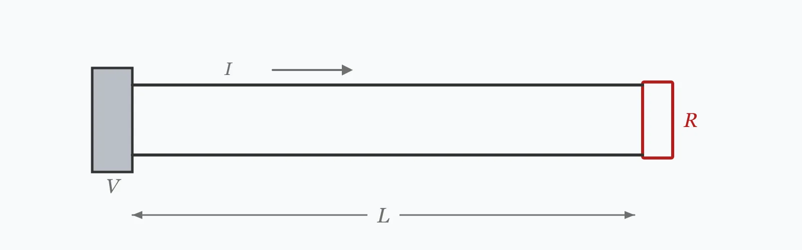
Single-phase voltage drop is VD = 2·I·R·L, the factor of two accounting for the current travelling out and back. Enter the supply voltage, load current, one-way cable length and the conductor's resistance per kilometre to get the drop in volts, as a percentage, the voltage remaining at the load, and the power wasted in the cable.
Calculator
Units:
V
Nominal supply voltage at the origin of the circuit
A
Design current of the circuit
m
Route length from supply to load, not the loop length
Press Calculate for the voltage drop in volts and as a percentage, the voltage remaining at the load, and the power dissipated in the cable. The percentage is what codes are written against.
Step-by-Step Solution
Preliminary design aid. Results follow the published formulas cited
below and are intended for estimating, study and early design. Final design must be
verified by a licensed Professional Engineer against the code in force for your project.
Key Benefits
✓Applies the single-phase formula with the correct factor of two for the return path
✓Reports the drop as a percentage, the form limits are written in
✓Warns automatically above the NEC 3% branch and 5% total thresholds
✓Returns the power lost in the cable, which is a continuous energy cost
✓Sensitivity chart shows the linear relationship with cable length
✓Shareable links and CSV export for installation records
What Is Voltage Drop?
Every conductor has resistance, so current flowing through it produces a voltage drop by Ohm's law. In a single-phase circuit the current travels out along one conductor and back along the other, so the resistance in the loop is twice that of a single run — hence VD = 2·I·R·L, with R the resistance per unit length and L the one-way distance.
Why the limits exist
Equipment is designed to operate within a voltage tolerance, and excessive drop pushes it outside. Motors run hotter and produce less torque, which falls with the square of voltage. Lighting dims and, with some drivers, flickers. Electronic supplies compensate by drawing more current, which increases the drop further. The NEC recommends 3% for a branch circuit and 5% overall from service to load, and most national codes set something similar.
Three-phase is different
This calculation uses the single-phase factor of two. A balanced three-phase circuit has no return current in the neutral, and its line-to-line voltage drop uses √3 rather than 2 — about 13% less for the same current and cable. Applying the single-phase formula to a three-phase circuit therefore overstates the drop, which is conservative but wasteful, and applying the three-phase formula to a single-phase circuit is the dangerous direction.
Formula
VD = 2 · I · R · L / 1000
Single-phase voltage drop, with R in Ω/km and L the one-way length in metres
Related Formulas
VD = √3 · I · R · L / 1000
VD% = 100 · VD / V_supply
P_loss = 2 · I² · R · L / 1000
R_70 ≈ 1.20 · R_20
Variable Definitions
Symbol
Variable
Unit
Description
VD
Voltage Drop
V
Volts lost along the cable between supply and load.
I
Load Current
A
Design current of the circuit. Drop is directly proportional to it.
R
Conductor Resistance
Ω/km
Resistance per kilometre of one conductor, from cable tables at the relevant temperature.
L
One-Way Length
m
Route length from supply to load, not the total conductor length.
VD%
Percentage Drop
%
Drop as a fraction of supply voltage, compared against the 3% and 5% limits.
P_loss
Power Loss
W
Energy dissipated in the cable as heat, a continuous operating cost.
How to Use This Calculator
Use the one-way route lengthEnter the distance from supply to load. The factor of two for the return conductor is already in the formula, so entering the loop length doubles the answer.
Take resistance at operating temperatureCable tables give resistance at 20 °C and at the conductor's operating temperature, usually 70 or 90 °C. Copper is about 20% more resistive at 70 °C, and using the cold value understates the drop by that margin.
Use the design current, not the protective device ratingVoltage drop depends on the current actually flowing. Using a 32 A breaker rating for a 22 A load overstates the drop by nearly half and can push you into an unnecessary cable size.
Check both limitsThe NEC recommends 3% for a branch circuit and 5% from the service to the final load. A feeder and its branch circuit must satisfy the combined limit, so each has less than 5% available on its own.
Use the three-phase formula where it appliesThis calculation is single-phase. For a balanced three-phase circuit, multiply the result by √3/2 — about 0.866 — or use the three-phase expression directly. Applying the single-phase form to three-phase is conservative but wasteful.
Worked Examples
Example 1
A 240 V single-phase circuit carries 30 A over a 50 m run in 16 mm² copper, resistance 1.15 Ω/km at operating temperature. Check the voltage drop.
Step-by-Step Solution
Voltage drop: VD = 2 × I × R × L / 1000 = 2 × 30 × 1.15 × 50 / 1000
= 3,450 / 1000 = 3.45 V
As a percentage: 3.45 / 240 × 100 = 1.44%
Voltage at the load: 240 − 3.45 = 236.6 V
Power loss in the cable: P = 2 × I² × R × L / 1000 = 2 × 900 × 1.15 × 50 / 1000 = 103.5 W
Assessment: 1.44% is comfortably inside the 3% branch circuit recommendation.
The 103.5 W of loss is worth noting separately — running continuously that is about 900 kWh a year, dissipated as heat in the cable and paid for at the meter.
Example 2
The same 30 A load and 50 m run, but in 2.5 mm² cable at 7.41 Ω/km. This shows why volt drop rather than current rating often sets the cable size.
Step-by-Step Solution
Voltage drop: VD = 2 × 30 × 7.41 × 50 / 1000 = 22.23 V
As a percentage: 22.23 / 240 × 100 = 9.26%
Voltage at the load: 240 − 22.23 = 217.8 V
Power loss: 2 × 900 × 7.41 × 50 / 1000 = 667 W
Assessment: 9.26% is more than three times the 3% recommendation and well beyond the 5% overall limit. The load would see 218 V instead of 240.
The consequence for a motor is worse than the number suggests: torque falls with the square of voltage, so 91% of nominal voltage gives only 82% of rated torque.
And 667 W of continuous loss is roughly 5,800 kWh a year — the cable is acting as a 667 W heater along its whole length.
Note that 2.5 mm² would be a perfectly legal current rating for 30 A in some installation methods. Volt drop, not ampacity, is what rules it out here.
Cable Length Sensitivity
Voltage drop rises linearly with cable length, so the percentage line is straight. Watch where it crosses 3% — that intersection is the maximum run length for this cable and load. The marker shows your current length.
Voltage Drop % vs One-Way Length (L)
Recomputed live from your inputs. The marker shows your current value.
Line chart of Voltage Drop % against One-Way Length (L). The same
values are listed in the data table below.
Values plotted above, sampled across the one-way length (l) range.
How to Interpret Your Results
The percentage drop is what codes are written against, and the two thresholds serve different purposes: 3% preserves equipment performance on a branch circuit, and 5% is the overall budget from the origin of the installation.
Voltage Drop %: < 1Very low drop
A drop of your result% is minimal. The cable is generously sized for this run, which is often the right answer where the load may grow or where the circuit runs continuously and the loss is a real cost.
Voltage Drop %: 1 – 3Within the branch circuit recommendation
A drop of your result% satisfies the NEC 3% branch circuit recommendation. Confirm the combined feeder and branch drop stays within the 5% overall limit, since the two are budgeted together.
Voltage Drop %: 3 – 5Exceeds the branch limit but within 5%
A drop of your result% is above the 3% branch circuit recommendation, though still inside the 5% overall limit. Acceptable only if the upstream feeder drop is very small. For motor loads, note that torque falls with the square of voltage.
Voltage Drop %: 5 – 10Exceeds the overall limit
A drop of your result% is beyond the 5% total limit. Equipment will operate below its design voltage: motors run hot and lose torque, lighting dims, and electronic supplies draw more current, which worsens the drop further. Increase the conductor size.
Voltage Drop %: ≥ 10Severe voltage drop
A drop of your result% is severe. At this level, motor starting may fail entirely and the cable is dissipating substantial heat along its length. Verify the inputs, then increase the conductor size or shorten the run — the drop is directly proportional to both.
Power Loss: ≥ 500Substantial cable loss
A loss of your result W is being dissipated in the cable itself. Running continuously, that is roughly your result × 8.76 kWh a year, paid for and delivering nothing. On a long or heavily loaded run, the larger cable often pays for itself in energy alone.
Common Mistakes to Avoid
Entering the loop length instead of the one-way run
Why it matters:The factor of two for the return conductor is already in the formula. Entering the total conductor length doubles the answer, which pushes cable sizing two or three steps larger than necessary.
✓How to avoid it:Enter the route distance from supply to load. If your result seems twice what a manufacturer's table gives, this is why.
Using the single-phase formula for a three-phase circuit
Why it matters:Balanced three-phase uses √3 rather than 2, giving about 13% less drop for the same current and cable. The single-phase result is conservative, so it does not create a safety issue, but it does specify unnecessary copper.
✓How to avoid it:Multiply the single-phase result by 0.866 for a balanced three-phase circuit, or use the three-phase expression directly.
Using the 20 °C resistance value
Why it matters:Cables run warm, and copper resistance rises about 0.4% per degree. At a 70 °C operating temperature the resistance is roughly 20% above the cold value, so the drop is understated by the same margin.
✓How to avoid it:Use the operating-temperature resistance from the cable table. Most tables publish both values precisely because this distinction matters.
Sizing on ampacity alone
Why it matters:A cable can carry its rated current safely and still lose too much voltage over a long run. In the example above, 2.5 mm² is legal for 30 A in some installation methods yet gives a 9.26% drop at 50 m.
✓How to avoid it:Check both criteria and take the larger cable. On runs beyond roughly 20 to 30 m, volt drop frequently governs rather than ampacity.
Ignoring motor starting current
Why it matters:A direct-on-line motor draws six to eight times its running current at start. The resulting momentary drop can be enough to prevent the motor developing starting torque, or to dip the voltage for other equipment on the same supply.
✓How to avoid it:Check the drop at starting current as well as running current. Codes generally permit a larger transient drop, but it must still allow the motor to start.
Overlooking the power loss as a cost
Why it matters:Volt drop compliance is a pass or fail check, but the loss behind it is continuous. A 667 W loss running all year is roughly 5,800 kWh, which often exceeds the cost difference between cable sizes within the first year.
✓How to avoid it:On continuously loaded circuits, compare the cost of the loss against the cost of the larger cable. The economic size is frequently above the compliant minimum.
Practical Applications
▸Sizing cables for branch circuits and sub-mains
▸Checking long runs to outbuildings and remote plant
▸Verifying existing installations against code limits
▸Assessing motor supply cables for starting performance
▸Estimating cable energy losses for operating cost
▸Determining maximum run length for a given cable size
Industry Use Cases
Building electrical installation
Volt drop is checked on every circuit but only governs on the long ones. Designers work out the maximum length for each cable size and load, then treat that as a rule of thumb during layout rather than recalculating each circuit.
Agricultural and remote supplies
Supplies to outbuildings routinely run hundreds of metres, where volt drop dominates completely. The usual remedy is to distribute at a higher voltage and transform down locally, since drop as a percentage falls with the square of the distribution voltage.
Motor installations
Direct-on-line starting draws six to eight times running current, and the momentary drop can prevent the motor developing enough torque to start at all. Cables to motors are therefore checked at both running and starting current.
Expert Tips
💡Enter the one-way route length — the factor of two for the return is already in the formula.
💡Multiply by 0.866 for a balanced three-phase circuit.
💡Use the operating-temperature resistance; copper is 20% more resistive at 70 °C than at 20 °C.
💡Beyond about 20 to 30 m, volt drop rather than ampacity usually sets the cable size.
💡Motor torque falls with the square of voltage — a 9% drop costs 18% of torque.
💡The power loss is a continuous cost; on long runs the larger cable often pays for itself.
Advantages & Limitations
Advantages
✓Direct application of Ohm's law with the correct loop factor
✓Reports both volts and percentage, the latter being what codes use
✓Returns the power loss, turning a compliance check into an economic one
✓Applies to any conductor material through the resistance input
✓Fast enough to check every circuit during design
Limitations
!Single-phase only; balanced three-phase needs the √3 factor
!Assumes a purely resistive load, ignoring reactance and power factor
!Uses the resistance value entered, so temperature correction is the user's responsibility
!Considers one circuit in isolation, not the cumulative drop through feeder and branch
!Takes no account of motor starting current or other transients
!Assumes a balanced load; unbalanced three-phase carries neutral current this does not model
!Does not check ampacity, which is a separate and independent requirement
Voltage Drop by Conductor Size
A 30 A load over 50 m at 240 V single-phase, in copper at operating temperature. Only 10 mm² and above satisfy the 3% branch recommendation, though smaller sizes may be perfectly adequate on current rating alone.
Copper at 70 °C, single-phase 240 V, 30 A over 50 m one-way. Resistance values are indicative — use your cable manufacturer's data.
For single-phase, VD = 2·I·R·L/1000 with R in Ω/km and L the one-way length in metres. A 30 A load over 50 m in 16 mm² copper at 1.15 Ω/km gives 3.45 V, or 1.44% of a 240 V supply.
What is the maximum allowable voltage drop?
The NEC recommends 3% for a branch circuit and 5% total from the service to the final load. Most national codes set similar figures — the UK wiring regulations use 3% for lighting and 5% for other uses.
Why is there a factor of two in the formula?
Because current flows out along one conductor and back along the other, so the loop resistance is twice that of a single run. Enter the one-way route length and the formula accounts for the return path itself.
How is three-phase voltage drop different?
A balanced three-phase circuit uses √3 rather than 2, giving about 13% less drop for the same current and cable. There is no return current in the neutral when the load is balanced, which is what removes the second conductor from the loop.
Does voltage drop affect motor performance?
Substantially. Motor torque falls with the square of voltage, so a 9% drop costs 18% of torque. It also raises the current drawn for a given mechanical output, which increases the drop further and makes the motor run hotter.
Should I size cables on current or voltage drop?
On both, taking the larger result. Ampacity is a safety requirement and volt drop a performance one. Beyond roughly 20 to 30 m, volt drop usually governs — a cable can be legal on current rating and still deliver too little voltage.
What resistance value should I use?
The one at conductor operating temperature, typically 70 or 90 °C, not the 20 °C table value. Copper is about 20% more resistive at 70 °C, and using the cold figure understates the drop by that margin.
How much energy does voltage drop waste?
The power lost is the drop times the current. A 22 V drop at 30 A is 667 W, which running continuously is roughly 5,800 kWh a year — often more than the cost difference between cable sizes.
How do I reduce voltage drop?
Increase the conductor size, shorten the run, or distribute at a higher voltage. Drop is inversely proportional to conductor area and directly proportional to length and current, so all three are available levers.
Do I need to check starting current for motors?
Yes. Direct-on-line starting draws six to eight times running current, and the resulting momentary drop can prevent the motor developing enough torque to start. Codes allow a larger transient drop, but starting must still be achievable.
Glossary
Voltage drop
The loss of voltage along a conductor caused by its resistance and the current flowing through it.
One-way length
The route distance from supply to load, as distinct from the total conductor length in the loop.
Ampacity
The current a conductor can carry continuously without exceeding its temperature rating.
Branch circuit
The final circuit between the last protective device and the load, subject to the 3% recommendation.
Feeder
A circuit between the service equipment and a branch circuit distribution point.
Operating temperature
The conductor temperature at rated current, typically 70 or 90 °C, at which resistance should be evaluated.
Balanced three-phase
A three-phase load drawing equal current in each phase, so no current returns through the neutral.
Direct-on-line starting
Applying full voltage to a motor at start, drawing six to eight times running current.
Temperature coefficient
The fractional rise in resistance per degree; about 0.4% per °C for copper.
Scientific & Standards References
NFPA 70 (National Electrical Code) Article 210.19(A) Informational Note — Branch circuit voltage drop — National Fire Protection Association
NFPA 70 Article 215.2(A) Informational Note — Feeder voltage drop — National Fire Protection Association
IEC 60364-5-52 — Selection and erection of wiring systems — International Electrotechnical Commission
IEC 60228 — Conductors of insulated cables — International Electrotechnical Commission
BS 7671 Appendix 4 — Current-carrying capacity and voltage drop for cables — Institution of Engineering and Technology
Conclusion
Single-phase voltage drop is 2·I·R·L, with the factor of two accounting for the return conductor, and the percentage it produces is what codes are written against — 3% for a branch circuit, 5% overall. The point worth carrying is that ampacity and volt drop are independent requirements, and beyond roughly 20 to 30 m it is volt drop that governs: a cable can be perfectly legal on current rating and still deliver 218 V to a 240 V load. Two adjustments are easy to miss. Use the resistance at operating temperature, since copper is 20% more resistive at 70 °C than cold. And for balanced three-phase, multiply by 0.866 — the single-phase formula is conservative there, but it buys copper nobody needs.
Check your own circuit above, then sweep the cable length in the chart to find where it crosses the 3% line.