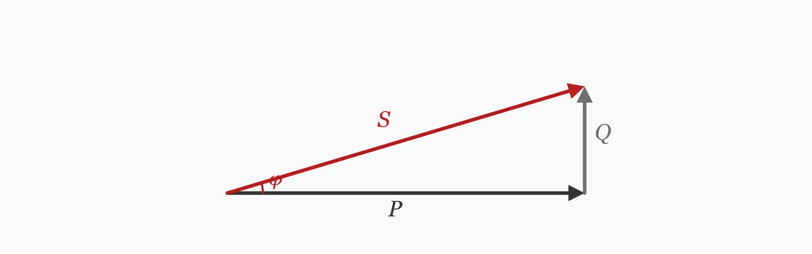
Correcting power factor means supplying the magnetising reactive power locally instead of drawing it from the network: Qc = P(tan φ₁ − tan φ₂). Enter the active power, the present and target power factors, the voltage and the frequency to get the capacitor rating in kVAr, the capacitance in microfarads, and the apparent power before and after.
Calculator
Units:
kW
Real power drawn by the load
From the meter or a power quality measurement
0.95 is the usual target; beyond 0.98 the return collapses
V
Voltage the capacitor bank is connected at
Hz
50 Hz or 60 Hz
Calculation Result
Press Calculate for the capacitor rating in kVAr, the equivalent capacitance, and the apparent power before and after correction. The reduction in kVA is the reduction in current, since the two are proportional at fixed voltage.
Step-by-Step Solution
Preliminary design aid. Results follow the published formulas cited
below and are intended for estimating, study and early design. Final design must be
verified by a licensed Professional Engineer against the code in force for your project.
Key Benefits
✓Sizes the capacitor bank directly from present and target power factor
✓Gives both the kVAr rating and the capacitance in microfarads
✓Shows the apparent power before and after, which is what the meter sees
✓Warns against overcorrection, which is penalised as heavily as undercorrection
✓Sensitivity chart shows the steepening cost of each further improvement
✓Shareable links and CSV export for design records
What Is Power Factor Correction?
An inductive load — a motor, a transformer, a fluorescent ballast — draws two components of current. One does work; the other establishes the magnetic field and returns to the supply each cycle. The second does nothing useful but still flows in the cables, the transformer and the network, heating all of them. Power factor is the ratio of real power to apparent power, and correction means supplying that reactive component locally from a capacitor rather than dragging it through the whole supply chain.
Why the formula uses tangents
Real power P, reactive power Q and apparent power S form a right triangle, with cos φ = P/S and tan φ = Q/P. So the reactive power at a given real power is P·tan φ. Correcting from φ₁ to φ₂ means removing the difference, Qc = P(tan φ₁ − tan φ₂). Working in tangents keeps the real power fixed — which is the point, since correction changes what the supply must deliver without changing what the load does.
The steepening cost of the last few points
The tangent function grows without bound as the angle approaches 90°, and it flattens near zero. That asymmetry means the first improvement is cheap and the last is very expensive. Going from 0.75 to 0.90 removes 22.2 kVA of demand for 39.8 kVAr of capacitors; going from 0.98 to unity removes only 2.0 kVA for a further 20.3 kVAr. Per kVA saved, the cost rises from 1.8 kVAr to 9.9.
Formula
Qc = P · (tan φ₁ − tan φ₂)
Capacitor reactive power needed to move from power factor cos φ₁ to cos φ₂
Related Formulas
φ = arccos(PF)
S = P / cos φ
C = Qc / (2π · f · V²)
I₂/I₁ = cos φ₁ / cos φ₂
Variable Definitions
Symbol
Variable
Unit
Description
P
Active Power
kW
Real power doing work. Unchanged by correction.
Qc
Capacitor Rating
kVAr
Reactive power the capacitor bank must supply.
cos φ₁
Initial Power Factor
—
Present power factor, from the meter or a measurement.
cos φ₂
Target Power Factor
—
Desired value. 0.95 is the usual practical target.
S
Apparent Power
kVA
Voltage times current — what the supply must deliver.
C
Capacitance
µF
Equivalent capacitance at the stated voltage and frequency.
How to Use This Calculator
Measure the present power factor, don't assume itPower factor varies with load, so a single nameplate figure does not represent an installation. Utility bills often state it, and a power quality logger over a working week gives the pattern — including whether the poor factor is constant or confined to particular operating states.
Use the average active power, not the peakThe capacitor bank should suit the load that actually persists. Sizing on a brief peak leads to overcorrection whenever that peak is absent, and a leading power factor is penalised by many tariffs just as a lagging one is.
Target 0.95, not unityThe return collapses beyond about 0.95. Correcting from 0.98 to unity costs almost as much capacitance as correcting from 0.75 to 0.90, and saves a tenth as much apparent power. Most tariffs stop penalising well before unity anyway.
Check what the load is made of firstWhere variable speed drives, rectifiers or LED lighting form a significant share, a plain capacitor bank can resonate with the supply inductance and amplify harmonic currents rather than reducing them. Detuned reactors are the standard remedy and should be assumed rather than added later.
Consider where the capacitors goCorrection at the main switchboard reduces the supply demand and the bill. Correction at each motor also unloads the internal distribution and reduces cable losses within the building, but it is more expensive and it must switch with the motor to avoid overcorrection at light load.
Worked Examples
Example 1
A 100 kW industrial load runs at a power factor of 0.75 on a 400 V, 50 Hz supply. Correct it to 0.95.
Reduction: 28.07 kVA, or 21.1% — and current falls by the same 21.1%, since the two are proportional
Capacitance at 400 V, 50 Hz: C = 55,320 / (2π × 50 × 400²) = 1,101 µF
Interpretation: 55 kVAr of capacitors removes 28 kVA of demand — 1.97 kVAr per kVA saved. That ratio is the number to watch as the target rises.
Example 2
The same 100 kW load, but correcting all the way to unity instead of stopping at 0.95 — the comparison that decides where to stop.
Step-by-Step Solution
Target angle: φ₂ = arccos(1.00) = 0°, tan φ₂ = 0
Capacitor rating: Qc = 100 × (0.8819 − 0) = 88.19 kVAr, against 55.32 kVAr for the 0.95 target
Apparent power after: 100 / 1.00 = 100.00 kVA, against 105.26 kVA
So the extra 32.87 kVAr of capacitors buys a further 5.26 kVA of reduction
That is 6.25 kVAr per kVA saved, against 1.97 for the correction up to 0.95 — more than three times the cost for each unit of benefit.
Taken step by step the deterioration is sharper still. The move from 0.98 to unity alone costs 20.30 kVAr and saves only 2.04 kVA: 9.95 kVAr per kVA, five times the rate of the first stretch.
There is also a risk that the arithmetic does not show. A bank sized for unity at full load overcorrects whenever the load drops, pushing the power factor leading — which many tariffs penalise identically, and which can raise the voltage on a lightly loaded feeder.
Target Power Factor Sensitivity
The capacitor rating rises gently at first and then steeply as the target approaches unity, while the apparent power it saves flattens out. The gap between those two curves is the whole economic case for stopping at 0.95. The marker shows your current target.
Capacitor Rating vs Target Power Factor
Recomputed live from your inputs. The marker shows your current value.
Line chart of Capacitor Rating against Target Power Factor. The same
values are listed in the data table below.
Values plotted above, sampled across the target power factor range.
How to Interpret Your Results
The capacitor rating is the answer, but the ratio of kVAr spent to kVA saved is what tells you whether the target is sensible. That ratio worsens sharply as the target approaches unity.
Capacitor Rating: < 0No correction needed
The target is not better than the present power factor, so no capacitors are required. Check the two values have not been entered the wrong way round.
Capacitor Rating: 0 – 25Small bank
A rating of your result kVAr is a modest bank, often a fixed unit rather than an automatically switched one. Confirm the load is reasonably steady — a fixed bank overcorrects whenever the load falls below what it was sized for.
A rating of your result kVAr suits automatic switching in steps, so the correction tracks the load through the day. Check the harmonic content before specifying plain capacitors, since drives and rectifiers make resonance a real risk at this scale.
Capacitor Rating: ≥ 200Large bank — study the network first
A rating of your result kVAr is large enough to interact with the supply network. A resonance study is warranted, and detuned reactors should be assumed rather than considered optional. Consider correcting at several points rather than in one block.
Apparent Power After: ≥ 0Demand after correction
The supply now delivers your result kVA for the same useful output. Current falls in the same proportion, which reduces cable and transformer losses as well as any demand charge — the losses fall with the square of current, so the saving there is larger than the ratio suggests.
Common Mistakes to Avoid
Correcting to unity
Why it matters:The cost per unit of benefit rises steeply near unity. The last step from 0.98 costs 9.95 kVAr for each kVA saved, against 1.8 at the start, and a bank sized for unity at full load will overcorrect at part load.
✓How to avoid it:Target 0.95, or whatever the tariff stops penalising. Leaving a small lagging margin is deliberate, not a compromise.
Ignoring harmonics
Why it matters:Capacitors present a falling impedance to rising frequency, so they form a resonant circuit with the supply inductance. If that resonance lands near a harmonic the load produces — commonly the 5th or 7th — the harmonic current is amplified rather than absorbed, overheating the capacitors and everything else.
✓How to avoid it:Assess the harmonic content before specifying. Detuned reactors shift the resonance below the lowest significant harmonic and are standard practice wherever drives or rectifiers form a meaningful share of the load.
Sizing on peak load with a fixed bank
Why it matters:A fixed capacitor bank supplies the same reactive power regardless of load. Sized for the peak, it overcorrects at every lighter condition, driving the power factor leading — penalised by many tariffs, and capable of raising voltage on a lightly loaded feeder.
✓How to avoid it:Use automatic switching in steps for a varying load, or size a fixed bank on the minimum sustained load rather than the maximum.
Correcting instead of fixing the cause
Why it matters:A very poor power factor often means motors are oversized and running at part load, where power factor collapses. Capacitors treat the symptom and leave the underlying inefficiency — and the oversized motor is also wasting energy through poor part-load efficiency.
✓How to avoid it:Investigate loading first. Right-sizing motors or fitting variable speed drives addresses both the power factor and the energy consumption; capacitors address only the former.
Assuming correction reduces the energy bill
Why it matters:Correction reduces apparent power and current, not real power. The kWh consumed by the load is unchanged, so the saving comes from demand charges, reactive power penalties, and reduced losses in cables and transformers — not from the energy itself.
✓How to avoid it:Check what the tariff actually charges for. Where there is no kVA or reactive penalty, the benefit is limited to loss reduction and released capacity, which may still justify the work but on a different basis.
Leaving capacitors permanently connected to a switched motor
Why it matters:A motor disconnected from the supply while still turning can be self-excited by attached capacitors, generating voltage at an uncontrolled frequency. Reconnecting out of phase then produces severe transient torque and current.
✓How to avoid it:Switch the capacitors with the motor and size them below the motor's own magnetising kVAr, which is the standard rule for individual correction.
Practical Applications
▸Sizing capacitor banks for power factor correction
▸Estimating the demand reduction from a proposed correction
▸Comparing correction targets on cost and benefit
▸Checking an existing bank against the present load
▸Assessing released supply capacity before an expansion
▸Evaluating reactive power penalties on a utility bill
Industry Use Cases
Manufacturing
Motor-heavy plants typically run at 0.7 to 0.8 uncorrected. Automatic banks switch in steps as the load varies through the shift, and the released transformer capacity is often as valuable as the tariff saving — it can defer a supply upgrade entirely.
Commercial buildings
Modern buildings have far more electronic load than motor load, so the traditional lagging power factor problem is often replaced by a harmonic one. Fitting plain capacitors to such a site can make matters worse, which is why the load composition is assessed before the correction is specified.
Distribution networks
Reactive power flowing through a network consumes capacity and causes voltage drop without delivering energy. Network operators price it accordingly, which is what makes correction economic for the consumer and beneficial for the network at the same time.
Expert Tips
💡Correction changes what the supply delivers, not what the load consumes.
💡Target 0.95 — beyond it the cost per kVA saved rises several-fold.
💡Current falls in the same proportion as apparent power, so losses fall with its square.
💡A fixed bank sized for peak load overcorrects at every lighter condition.
💡Capacitors plus drives can resonate; detuned reactors are the standard remedy.
💡Very poor power factor usually means oversized motors at part load.
Advantages & Limitations
Advantages
✓Sizes the bank directly from the two power factors and the real power
✓Gives both kVAr and capacitance, so the result can be specified either way
✓Shows apparent power before and after, which is what the meter records
✓Warns explicitly about overcorrection and about harmonic resonance
✓Makes the diminishing return near unity visible rather than implicit
Limitations
!Assumes a steady load at a single power factor
!Capacitance is given for a single-phase bank at line voltage; three-phase delta and star banks differ
!Takes no account of harmonics, which can make plain capacitors counterproductive
!Does not size switching steps for an automatic bank
!Assumes a lagging power factor; a leading one needs inductive compensation instead
!Does not evaluate the tariff, which determines whether correction pays
!Gives no guidance on where in the installation the correction should sit
The Cost of Each Further Improvement
A 100 kW load at 0.75, corrected to progressively higher targets. The final column is the one that matters: how many kVAr of capacitors each kVA of demand reduction costs.
100 kW load at 400 V, 50 Hz, starting from 0.75. Each step's cost is the additional kVAr divided by the additional kVA saved. The first stretch to 0.90 costs 1.79 kVAr per kVA; the last to unity costs 9.95 — five and a half times the rate, for less than a tenth of the demand reduction.
Qc = P × (tan φ₁ − tan φ₂), where the angles come from the present and target power factors. A 100 kW load at 0.75 corrected to 0.95 needs 55.32 kVAr.
What is power factor?
The ratio of real power to apparent power, cos φ. It measures how much of the current delivered actually does work; the rest establishes magnetic fields and returns to the supply each cycle.
What power factor should I correct to?
0.95 is the usual target. Beyond it the cost per unit of benefit rises steeply — correcting the last step from 0.98 to unity costs nearly six times as much capacitance per kVA saved as the first stretch.
Does power factor correction save energy?
Not directly. It reduces apparent power and current, not the real power the load consumes. The savings come from demand and reactive charges, released supply capacity, and reduced losses in cables and transformers.
What is overcorrection?
Supplying more reactive power than the load needs, so the power factor becomes leading. Many tariffs penalise it identically to a lagging factor, and it can raise the voltage on a lightly loaded feeder.
How much capacitance is a kVAr?
It depends on voltage and frequency: C = Qc/(2πfV²). At 400 V and 50 Hz, 55.32 kVAr is about 1,101 µF for a single-phase bank.
Why do capacitors and harmonics interact badly?
Capacitor impedance falls with frequency while supply inductance rises, so together they resonate. If that resonance falls near a harmonic the load produces, the harmonic current is amplified rather than absorbed, overheating the capacitors.
What is a detuned reactor?
An inductor in series with the capacitor bank that shifts the resonant frequency below the lowest significant harmonic, usually the 5th. It is standard wherever variable speed drives or rectifiers form a meaningful part of the load.
Should capacitors go at the switchboard or at each motor?
At the switchboard reduces the supply demand and the bill. At each motor also unloads the internal distribution and cuts cable losses, but costs more and must switch with the motor to avoid overcorrection at light load.
How much does correction reduce the current?
In the same proportion as the apparent power. Correcting from 0.75 to 0.95 reduces current by 21.1%, and since losses go with the square of current, cable and transformer losses fall by about 38%.
Glossary
Power factor
The ratio of real power to apparent power, cos φ.
Real power
Power that does work, measured in kW — unchanged by correction.
Reactive power
Power that establishes magnetic fields and returns each cycle, measured in kVAr.
Apparent power
Voltage times current, in kVA — what the supply must deliver.
Lagging power factor
Current lagging voltage, characteristic of inductive loads such as motors.
Leading power factor
Current leading voltage, the result of overcorrection.
Detuned reactor
An inductor in series with a capacitor bank to move the resonance away from load harmonics.
Automatic bank
A capacitor bank switched in steps to follow a varying load.
Released capacity
Supply capacity freed by correction, available for additional load.
Self-excitation
A disconnected motor generating voltage from attached capacitors while still turning.
Scientific & Standards References
IEC 61921 — Power capacitors: Low-voltage power factor correction banks — International Electrotechnical Commission
IEEE 1036 — Guide for the Application of Shunt Power Capacitors — Institute of Electrical and Electronics Engineers
IEEE 519 — Recommended Practice and Requirements for Harmonic Control in Electric Power Systems — Institute of Electrical and Electronics Engineers
IEC 60831 — Shunt power capacitors of the self-healing type for AC systems — International Electrotechnical Commission
Schneider Electric, Electrical Installation Guide — Power Factor Correction and Harmonic Filtering — Schneider Electric
Conclusion
Sizing a capacitor bank is one subtraction of tangents, and the shape of the tangent function is what makes the answer interesting. Because tan φ flattens near zero and grows without bound near 90°, the first improvement in power factor is cheap and the last is very expensive: the table above shows 1.79 kVAr per kVA saved on the way to 0.90 and 9.95 on the way from 0.98 to unity. That is the whole reason 0.95 is the conventional target — not caution, but a return that has genuinely collapsed by then. Two things this arithmetic cannot see decide whether correction is a good idea at all. Harmonics, because capacitors resonate with supply inductance and can amplify the very currents they were meant to reduce. And the cause of the poor power factor, because a figure of 0.6 or 0.7 usually means motors running well below their rating, where capacitors treat the symptom and leave the waste in place.
Enter your load and present power factor above to size a bank and see the trade-off.