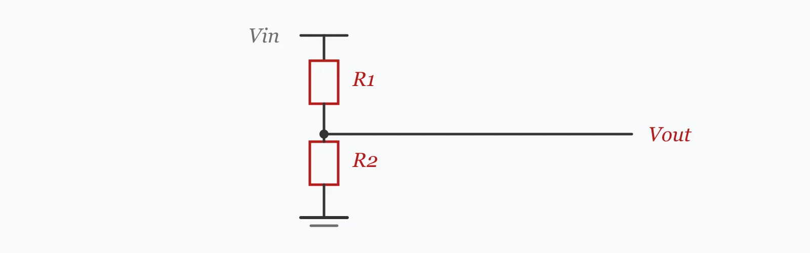
A resistive divider outputs Vin × R₂/(R₁+R₂) — but only when nothing is connected to it. Enter the input voltage, the two resistors and the load resistance to get the loaded output, the unloaded ideal, the current drawn and the loading error. The load sits in parallel with R₂, and that is where most divider designs go wrong.
Calculator
Units:
V
Supply across the resistor pair
Ω
Between the supply and the output node
Ω
Between the output node and ground
Ω
Input resistance of the circuit being fed. Use a very large value for none
Calculation Result
Press Calculate for the loaded output voltage, the unloaded ideal, the current flowing through the divider, and the loading error. A negative error means the load has pulled the output below the textbook value.
Step-by-Step Solution
Preliminary design aid. Results follow the published formulas cited
below and are intended for estimating, study and early design. Final design must be
verified by a licensed Professional Engineer against the code in force for your project.
Key Benefits
✓Shows loaded and unloaded output side by side, which is the whole point
✓Reports the loading error as a percentage rather than leaving it to be inferred
✓Gives the quiescent current, which matters for battery-powered designs
✓Warns when the load resistance is too low for a resistive divider to work
✓Sensitivity chart shows the error growing as the load gets heavier
✓Shareable links and CSV export for design records
What Is Voltage Divider?
Two resistors in series across a supply divide the voltage in proportion to their resistances. The junction between them sits at Vin × R₂/(R₁+R₂), because the same current flows through both and each drops voltage in proportion to its own resistance. It is the simplest way to obtain a lower voltage from a higher one, and it needs no active components at all.
Why a load changes the answer
Anything connected to the output draws current, and that current does not come from nowhere — it comes through R₁. Electrically, the load resistance sits in parallel with R₂, and the parallel combination is always smaller than either. So the effective R₂ shrinks, the ratio falls, and the output drops. With a 10 kΩ load on a 10 kΩ R₂, the parallel value is 5 kΩ and the output falls from 6 V to 4 V — a third lower.
The ten-times rule and what it costs
The conventional guidance is that the load should be at least ten times R₂, which keeps the error to a few percent. At exactly ten times the error is 4.76%; at a hundred times it is 0.50%; at a thousand times it is 0.05%. That is a useful scale to hold: each factor of ten in load resistance divides the error by roughly ten. Where the divider feeds a high-impedance input such as an op-amp or a modern microcontroller pin, the error effectively vanishes.
Formula
V_out = V_in · R₂ / (R₁ + R₂)
Unloaded divider output — the textbook formula, valid only with nothing connected
Related Formulas
R₂' = R₂ · R_L / (R₂ + R_L)
V_out = V_in · R₂' / (R₁ + R₂')
R_Thevenin = R₁ · R₂ / (R₁ + R₂)
P = V_in² / (R₁ + R₂)
Variable Definitions
Symbol
Variable
Unit
Description
V_in
Input Voltage
V
Supply voltage across the pair of resistors.
R₁
Upper Resistor
Ω
Between the supply and the output node.
R₂
Lower Resistor
Ω
Between the output node and ground.
R_L
Load Resistance
Ω
Input resistance of whatever the divider feeds.
V_out
Output Voltage
V
Voltage at the junction, with the load connected.
R_Th
Output Impedance
Ω
R₁ in parallel with R₂ — the Thevenin resistance seen by the load.
How to Use This Calculator
Enter the real load resistanceThis is the input resistance of whatever the divider feeds — an op-amp input is often gigaohms, a microcontroller ADC input typically tens of kilohms to megohms, and a bipolar transistor base a few kilohms. For a genuinely unloaded divider, enter a very large value.
Compare the loaded and unloaded figuresThe unloaded value is what the textbook formula gives. The gap between them is the error your circuit will actually experience, and it is a systematic offset in every reading rather than noise that averages out.
Check the divider current against your power budgetThe divider draws current continuously, whether or not the output is used. On a battery-powered design that quiescent draw may dominate the standby consumption, which pushes towards higher resistances.
Balance the two competing pressuresLower resistances reduce the loading error but waste more power. Higher resistances save power but become vulnerable to leakage, humidity across the board and the input bias current of whatever they feed. There is a practical window rather than a single right answer.
Remember a divider is not a regulatorThe output tracks the input exactly. If the supply moves 10%, the output moves 10%. A divider fed from an unregulated supply gives an unregulated output, which is a common oversight when it is used to make a reference voltage.
Worked Examples
Example 1
A 12 V supply divided by two 10 kΩ resistors, feeding a load of 100 kΩ — a typical microcontroller ADC input.
Interpretation: the load is ten times R₂, so the error lands at the 4.76% the ten-times rule implies. If this divider feeds an ADC, every reading is 4.76% low — a systematic offset, not random noise, so averaging will not remove it.
Example 2
The same divider feeding a much heavier load of 1 kΩ — a tenth of R₂ rather than ten times it.
The divider current has risen to 1.10 mA, most of which now flows into the load rather than through R₂
The output is a sixth of what the formula predicted. At this point the divider is not dividing anything — the load is setting the voltage and the resistors are merely limiting the current.
The fix is not a different ratio. Rescaling R₁ and R₂ downward until they dominate the load would work numerically, but a divider stiff enough for a 1 kΩ load would need resistances around 100 Ω and would burn well over a watt.
The right answer is a buffer: an op-amp voltage follower between the divider and the load presents a near-infinite input resistance, so the divider sees no load at all and delivers its unloaded 6.000 V.
Load Sensitivity
How the output and the error respond to the load resistance. The curve is steep at the left and flattens to the right — which is why the ten-times rule works, and why going far beyond it buys very little. The marker shows your current load.
Output Voltage (loaded) vs Load Resistance
Recomputed live from your inputs. The marker shows your current value.
Line chart of Output Voltage (loaded) against Load Resistance. The same
values are listed in the data table below.
Values plotted above, sampled across the load resistance range.
How to Interpret Your Results
The loading error is the result that matters. It tells you whether the divider is doing what the formula says, and whether a buffer is needed.
Loading Error: < -20The load, not the divider, is setting the voltage
A loading error of your result% means the divider is not working as one. The load resistance is comparable to or below R₂, so it dominates the parallel combination. Buffer the output with an op-amp follower, or use an active reference instead.
Loading Error: -20 – -5Substantial loading
A loading error of your result% is too large for anything where the value matters. The load should be at least ten times R₂; reduce the divider resistances or buffer the output. Rescaling the divider costs power, so a buffer is usually the better trade.
Loading Error: -5 – -0.5Small but systematic error
A loading error of your result% is modest but it is an offset, not noise — every reading is shifted the same way and averaging will not remove it. For an ADC reference or a measurement divider, calibrate it out or raise the load resistance.
Loading Error: ≥ -0.5Effectively unloaded
A loading error of your result% is negligible. The load resistance is high enough that the textbook formula applies. At this point resistor tolerance dominates the accuracy — 1% parts give up to 1% error in the ratio, twenty times this figure.
Divider Current: ≥ 5High quiescent current
The divider draws your result mA continuously, whether the output is used or not. On a battery-powered design this may dominate standby consumption. Higher resistances cut it proportionally, at the cost of more sensitivity to loading and leakage.
Common Mistakes to Avoid
Using the unloaded formula with a load connected
Why it matters:The textbook ratio describes an open-circuit output. Any load sits in parallel with R₂ and reduces the effective lower resistance, so the real output is always lower than the formula predicts — by 4.76% at ten times R₂ and by 83% at a tenth.
✓How to avoid it:Compute with the parallel combination, as this calculator does. Check the load's input resistance from its datasheet rather than assuming it is high.
Using a divider as a voltage regulator
Why it matters:A divider is a fixed ratio, not a regulator. The output tracks the input exactly, so a 10% supply variation produces a 10% output variation, and any change in load current changes it further.
✓How to avoid it:Use a voltage reference or a regulator where the output must be stable. A divider is only appropriate where the input is already regulated and the load is light and constant.
Choosing resistances without considering both failure modes
Why it matters:Low resistances waste power continuously; high resistances become vulnerable to leakage, surface contamination on the board, and the input bias current of whatever they feed. Both extremes fail, in opposite ways.
✓How to avoid it:Aim for a divider current comfortably above the load's input bias current but low enough for the power budget — often tens of microamps to a milliamp for signal-level dividers.
Forgetting the divider's output impedance
Why it matters:R₁ in parallel with R₂ is the Thevenin resistance the load sees, and it also forms a low-pass filter with any capacitance at the output. A high-impedance divider feeding a sampling ADC may not settle within the sampling window.
✓How to avoid it:Check the output impedance against the ADC's source impedance requirement, typically a few kilohms. Add a buffer or reduce the resistances where it is exceeded.
Ignoring resistor tolerance
Why it matters:Once loading is eliminated, tolerance dominates. Two 1% resistors can give a ratio error of up to about 1%, which is twenty times the 0.05% loading error of a well-designed divider.
✓How to avoid it:Use 0.1% parts where the ratio matters, or calibrate. A matched resistor pair in one package also tracks better over temperature than two separate parts.
Dividing a high voltage without considering the resistor ratings
Why it matters:A divider across a high voltage puts most of it across R₁, and standard resistors have maximum working voltage ratings — often 200 to 400 V — independent of their power rating. A part within its wattage can still arc over.
✓How to avoid it:Use several resistors in series to share the voltage, or specify high-voltage parts. Check both the power and the working voltage rating.
Practical Applications
▸Scaling a voltage down for an ADC input
▸Setting a bias point in an amplifier circuit
▸Creating a reference voltage from a regulated supply
▸Level-shifting between logic families
▸Battery voltage monitoring in portable equipment
▸Setting the feedback ratio in a regulator circuit
Industry Use Cases
Embedded electronics
Battery monitoring divides the pack voltage down to the microcontroller's ADC range. The divider draws current continuously, so it is often switched by a transistor and only enabled during a measurement — which turns a persistent standby drain into a negligible one.
Instrumentation
Precision dividers use matched resistor networks in a single package, because two parts in one die track over temperature far better than two separate ones. Loading is eliminated with a buffer amplifier, leaving tolerance and drift as the accuracy limits.
Power supply design
Switching regulators set their output voltage with a feedback divider between the output and the control pin. The pin's input bias current sets the lower bound on divider current, which is why datasheets specify a maximum resistance for the lower resistor.
Expert Tips
💡The load sits in parallel with R₂ — that is the whole story.
💡Ten times R₂ gives 4.76% error; a hundred times gives 0.50%.
💡Loading error is a systematic offset, so averaging will not remove it.
💡A divider tracks its input exactly; it is a ratio, not a regulator.
💡Output impedance is R₁ parallel R₂ — check it against the ADC's requirement.
💡Once loading is solved, resistor tolerance becomes the accuracy limit.
Advantages & Limitations
Advantages
✓Shows the loaded and unloaded outputs together, which is where the misuse happens
✓Quantifies the loading error rather than leaving it as a rule of thumb
✓Reports the quiescent current, which matters for battery designs
✓Warns when the arrangement has stopped being a divider at all
✓Simple enough to check by hand during a design review
Limitations
!Assumes purely resistive components and a DC or low-frequency signal
!Takes no account of resistor tolerance, which usually dominates once loading is solved
!Ignores temperature coefficient and the drift between two dissimilar parts
!Does not model capacitance at the output, which affects settling time
!Assumes a linear load; a diode or transistor input is not one
!Does not check resistor power or working voltage ratings
!Says nothing about supply stability, which the output tracks directly
How Load Resistance Changes the Answer
A 12 V supply with two 10 kΩ resistors, which the textbook formula says gives 6 V. Each row changes only the load. Notice the pattern in the error column: every factor of ten in load resistance divides the error by roughly ten.
12 V input, R₁ = R₂ = 10 kΩ, unloaded output 6.000 V. The ten-times rule lands at 4.76% error — usable for a rough scaling, not for a measurement. The 1 kΩ row is the failure mode: the output is a sixth of the intended value, because the load has taken over from R₂ entirely.
Vout = Vin × R₂/(R₁+R₂) with nothing connected. With a load, replace R₂ by its parallel combination with the load resistance, which always lowers the output.
Why is my divider output lower than calculated?
Almost always because of loading. The connected circuit sits in parallel with R₂, reducing the effective lower resistance and therefore the ratio. A load equal to R₂ cuts the output by a third.
How large should the load resistance be?
At least ten times R₂ for a few percent error, and a hundred times for half a percent. Each factor of ten in load resistance divides the error by roughly ten.
Can I use a voltage divider as a power supply?
No. A divider has a high output impedance and no regulation, so the output collapses under any meaningful current and tracks every variation in the input. Use a regulator.
What is the output impedance of a divider?
R₁ in parallel with R₂. For two 10 kΩ resistors it is 5 kΩ, which is what the load sees and what determines how sensitive the output is to loading.
Should I use high or low resistance values?
It is a trade-off. Low values reduce loading error but waste power continuously; high values save power but become vulnerable to leakage, board contamination and input bias current. Signal dividers commonly land between tens of kilohms and a megohm.
How do I eliminate loading error entirely?
Buffer the output with an op-amp voltage follower. Its input resistance is high enough that the divider sees effectively no load, so it delivers the unloaded value while the op-amp supplies whatever current the real load needs.
How much power does a divider waste?
Vin²/(R₁+R₂), drawn continuously whether the output is used or not. A 12 V supply across two 10 kΩ resistors draws 0.6 mA and dissipates 7.2 mW — negligible on mains power, significant on a coin cell.
Does resistor tolerance matter?
It becomes the dominant error once loading is solved. Two 1% resistors can give a ratio error approaching 1%, which is twenty times the 0.05% loading error of a properly designed divider.
Can I use a divider on a high voltage?
Yes, but check the resistors' maximum working voltage as well as their power rating. Standard parts are often limited to 200 to 400 V regardless of wattage, so high-voltage dividers use several resistors in series to share the stress.
Glossary
Voltage divider
Two resistors in series whose junction provides a fraction of the supply voltage.
Loading error
The reduction in output caused by current drawn by the connected circuit.
Output impedance
R₁ in parallel with R₂ — the Thevenin resistance the load sees.
Thevenin equivalent
A representation of any linear network as one voltage source and one series resistance.
Voltage follower
An op-amp buffer with unity gain and very high input resistance, used to isolate a divider from its load.
Quiescent current
Current drawn continuously by the divider regardless of whether its output is used.
Input bias current
The small current an amplifier or ADC input draws, which loads a high-impedance divider.
Resistor tolerance
The permitted deviation from nominal value, which limits divider accuracy once loading is solved.
Settling time
The time for the output to reach its final value, set by the output impedance and any capacitance.
Working voltage
The maximum voltage a resistor may sustain, independent of its power rating.
Scientific & Standards References
Horowitz, P. and Hill, W., The Art of Electronics, 3rd Edition — Chapter 1: Foundations — Cambridge University Press
IEC 60063 — Preferred number series for resistors and capacitors — International Electrotechnical Commission
Analog Devices AN-1258 — Voltage Divider Design and Error Analysis — Analog Devices application note
Vishay Technical Note — Voltage Coefficient and Working Voltage of Film Resistors — Vishay Intertechnology
Conclusion
The divider formula everyone remembers describes a circuit with nothing connected to it, and the difference between that and reality is the whole subject. A load sits in parallel with R₂, so the effective lower resistance shrinks and the output falls — by 4.76% at the conventional ten-times-R₂ rule, and by 83% when the load is a tenth of R₂, at which point the load is setting the voltage and the resistors are just limiting current. Two things follow. First, that error is a systematic offset rather than noise, so it shifts every reading the same way and averaging cannot remove it. Second, the fix is usually a buffer rather than a different ratio: making a divider stiff enough for a heavy load means resistances low enough to burn real power, whereas an op-amp follower removes the load entirely. Once loading is solved, resistor tolerance takes over as the accuracy limit — and a 1% pair is twenty times worse than a well-loaded divider.
Enter your resistor values and the real load above to see the error before you build it.