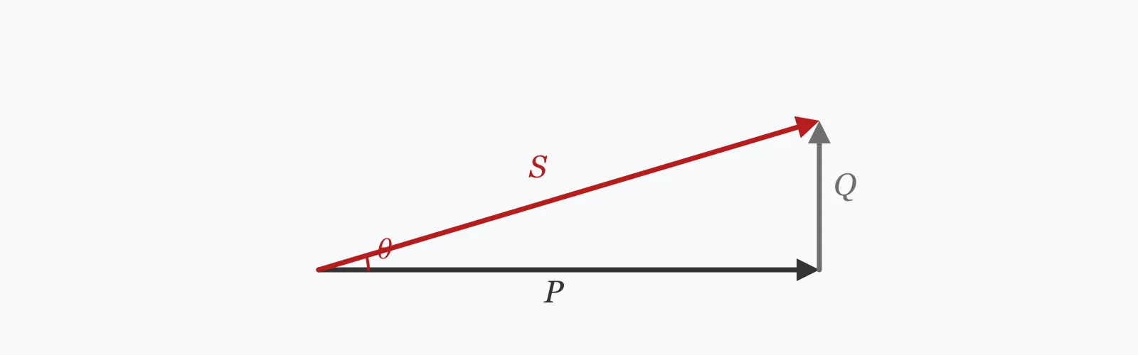
Power factor is the cosine of the angle between voltage and current: cos θ. Enter the voltage, current and phase angle to get the power factor, the apparent power in kVA, and its split into real power in kW and reactive power in kVAR. These are single-phase relationships — three-phase apparent power carries an additional √3.
Calculator
Units:
V
RMS supply voltage
A
RMS load current
°
0° resistive, 25.8° for PF 0.90, 36.9° for PF 0.80
Calculation Result
Press Calculate for the power factor, apparent power, real power and reactive power. Apparent power is what the supply must carry; real power is what does work; reactive power is the difference, and it is what correction removes.
Step-by-Step Solution
Preliminary design aid. Results follow the published formulas cited
below and are intended for estimating, study and early design. Final design must be
verified by a licensed Professional Engineer against the code in force for your project.
Key Benefits
✓Resolves apparent power into its real and reactive components
✓Returns the power factor directly from the phase angle
✓Warns automatically below 0.85, the usual correction threshold
✓Includes typical power factors for the common load types
✓Sensitivity chart shows how the split changes with phase angle
✓Shareable links and CSV export for electrical records
What Is Power Factor?
In an AC circuit containing inductance or capacitance, current and voltage do not peak at the same instant. The angle between them is the phase angle θ, and the power factor is its cosine. Apparent power S = VI is what the supply actually delivers; real power P = S·cos θ is what performs work; and reactive power Q = S·sin θ is what oscillates between source and load without net transfer. The three form a right triangle with S as the hypotenuse.
Why reactive power costs money
Reactive power does no useful work but it is entirely real to the cables, transformers and switchgear carrying it. A load at 0.7 power factor draws 43% more current than the same real power at unity, so every component in the supply path must be larger, and every one of them dissipates more heat. Utilities meter it or apply a penalty tariff precisely because it consumes network capacity that someone has paid to build.
How correction works
Inductive loads — motors, transformers, fluorescent ballasts — draw lagging reactive power. Capacitors supply leading reactive power, so connecting them in parallel cancels part of the inductive demand locally rather than importing it from the network. Correction from 0.7 to 0.95 typically cuts the current drawn by around a quarter, which frees capacity, reduces losses and removes the tariff penalty. Overcorrecting into a leading power factor is possible and causes its own problems, including voltage rise and resonance with system inductance.
Formula
PF = cos θ
Power factor as the cosine of the phase angle between voltage and current
Related Formulas
S = V × I / 1000
P = S · cos θ, Q = S · sin θ
S = √(P² + Q²)
Q_c = P(tan θ₁ − tan θ₂)
Variable Definitions
Symbol
Variable
Unit
Description
PF
Power Factor
—
Cosine of the phase angle; the fraction of apparent power that does useful work.
θ
Phase Angle
°
Angle by which current lags or leads voltage. Zero for a purely resistive load.
S
Apparent Power
kVA
The product of voltage and current — what the supply and its equipment must carry.
P
Real Power
kW
The component that performs useful work and appears on the energy meter.
Q
Reactive Power
kVAR
The component oscillating between source and load, doing no net work.
Q_c
Correction kVAR
kVAR
Capacitive reactive power needed to raise the power factor to a target value.
How to Use This Calculator
Enter RMS valuesVoltage and current must both be RMS, which is what any ordinary meter reads. Peak values would overstate the apparent power by a factor of two.
Obtain the phase angle from the power factor if neededIf you know the power factor rather than the angle, take its inverse cosine: 0.90 corresponds to 25.8 degrees and 0.80 to 36.9 degrees. Nameplate data usually quotes the power factor directly.
Note this is the single-phase relationshipApparent power here is V × I. A balanced three-phase system uses S = √3 × V_line × I_line, so multiply by 1.732 when working from line values. The power factor itself is unaffected.
Size correction from the reactive powerTo raise the power factor, add capacitors supplying Qc = P(tan θ₁ − tan θ₂). Correcting 20.78 kW from 0.866 to 0.95 needs about 5.2 kVAR of capacitance.
Do not overcorrectTarget 0.95 rather than unity. A leading power factor causes voltage rise on light load and can resonate with system inductance, particularly where variable speed drives inject harmonics. Automatic capacitor banks switch in stages to avoid it.
Worked Examples
Example 1
A single-phase load draws 50 A at 480 V with a phase angle of 30 degrees. Find the power factor and the power components.
Step-by-Step Solution
Apparent power: S = V × I / 1000 = 480 × 50 / 1000 = 24.00 kVA
Power factor: PF = cos 30° = 0.866
Real power: P = S × PF = 24.00 × 0.866 = 20.78 kW
Reactive power: Q = S × sin 30° = 24.00 × 0.500 = 12.00 kVAR
Check the triangle: √(20.78² + 12.00²) = √(431.8 + 144.0) = √575.8 = 24.00 kVA — closes correctly
Assessment: at 0.866 the load is just below the 0.9 threshold many tariffs use. Of the 24 kVA the supply carries, only 20.78 kW does work.
Correcting to 0.95 would need Qc = 20.78 × (tan 30° − tan 18.19°) = 20.78 × (0.5774 − 0.3287) = 5.17 kVAR.
Example 2
A lightly loaded induction motor at 0.50 power factor, drawing the same 24 kVA. This is the case that makes correction economic.
Step-by-Step Solution
Phase angle for PF 0.50: θ = 60 degrees
Apparent power is unchanged: S = 24.00 kVA
Real power: P = 24.00 × 0.500 = 12.00 kW
Reactive power: Q = 24.00 × sin 60° = 24.00 × 0.866 = 20.78 kVAR
The components have swapped compared with the first example: the load now draws more reactive than real power.
To deliver the same 12 kW at unity power factor would need only 12 kVA, so half the supply capacity is being consumed by reactive power alone.
Put another way, the current would fall from 50 A to 25 A. Since cable losses go as I², correcting this load would cut the distribution loss to a quarter.
This is why lightly loaded motors are the classic correction target: an induction motor at 25% load can fall to 0.5 power factor or worse, while the same motor near full load reaches 0.85.
Phase Angle Sensitivity
Apparent power stays fixed while real and reactive power trade against each other along the power triangle. They cross at 45 degrees, where the load is drawing as much reactive power as real. The marker shows your current phase angle.
Real Power (P) vs Phase Angle (θ)
Recomputed live from your inputs. The marker shows your current value.
Line chart of Real Power (P) against Phase Angle (θ). The same
values are listed in the data table below.
Values plotted above, sampled across the phase angle (θ) range.
How to Interpret Your Results
Power factor is read directly against tariff and design thresholds. Most utilities apply a penalty below 0.90 or 0.95, and the current drawn for a given real power is inversely proportional to it.
Power Factor: ≥ 0.95Excellent power factor
A power factor of your result is at or above the target most utilities set. Reactive demand is minimal and no correction is needed. Avoid pushing closer to unity, since overcorrection into a leading condition brings its own problems.
Power Factor: 0.85 – 0.95Acceptable power factor
A power factor of your result is typical of a well-loaded industrial installation. Some tariffs penalise below 0.95, so check the supply agreement — modest correction may still pay for itself.
Power Factor: 0.7 – 0.85Poor power factor — correction likely worthwhile
A power factor of your result means the supply carries substantially more current than the real power requires. Most tariffs penalise this range, and correction usually pays back within a year or two through the tariff alone.
Power Factor: < 0.7Very poor power factor
A power factor of your result means the supply is carrying at least 43% more current than the real power needs. Cables, transformers and switchgear are all oversized for the work being done, losses are elevated, and the tariff penalty will be significant. Correct it.
Reactive Power (Q): ≥ 50High reactive demand
A reactive demand of your result kVAR is substantial and occupies real network capacity. Sizing a capacitor bank against it typically releases transformer and cable capacity that would otherwise require reinforcement.
Common Mistakes to Avoid
Treating kVA and kW as interchangeable
Why it matters:They are equal only at unity power factor. A 24 kVA supply delivers just 12 kW at a power factor of 0.5, so sizing a transformer or generator on kW alone under-specifies it for any reactive load.
✓How to avoid it:Size supply equipment on kVA. Divide the real power demand by the expected power factor to obtain the apparent power the supply must carry.
Using the single-phase formula for three-phase
Why it matters:Balanced three-phase apparent power is √3 × V_line × I_line, not V × I. Omitting the √3 understates the apparent power by 42%.
✓How to avoid it:Multiply the apparent power by 1.732 when working from three-phase line values. The power factor itself is the same in both cases.
Correcting to unity
Why it matters:A capacitor bank sized for exactly unity at full load overcorrects at light load, producing a leading power factor. That raises voltage, can resonate with system inductance, and is penalised by some tariffs in the same way as lagging.
✓How to avoid it:Target 0.95. Use automatic staged banks that switch capacitance in and out to track the load rather than a fixed installation sized for peak.
Correcting at the wrong point in the network
Why it matters:Capacitors installed at the main intake relieve the utility supply but not the cables between the intake and the load, which continue to carry the reactive current.
✓How to avoid it:Correct as close to the inductive load as practical to relieve the whole distribution path. Individual motor correction gives the greatest benefit, at higher installation cost.
Ignoring harmonics when applying capacitors
Why it matters:Capacitors present a low impedance to harmonic currents, and can resonate with system inductance at a harmonic frequency. Where variable speed drives or rectifiers are present, plain capacitors can be destroyed or cause serious distortion.
✓How to avoid it:Use detuned reactors in series with the capacitors where significant harmonic sources exist. A harmonic survey before installing correction is standard practice on any modern installation.
Assuming power factor is constant with load
Why it matters:Induction motor power factor falls sharply at part load — a motor at 0.85 near full load may drop to 0.5 or worse at a quarter load. Fixed correction sized at full load overcorrects badly at light load.
✓How to avoid it:Correct for the typical operating condition rather than the nameplate, or use automatic switching. Right-sizing oversized motors often improves power factor more cheaply than correcting them.
Practical Applications
▸Assessing whether power factor correction is economic
▸Sizing capacitor banks for industrial installations
▸Determining transformer and generator capacity for reactive loads
▸Checking supply tariff penalties against measured power factor
▸Estimating current reduction from proposed correction
▸Analysing motor performance across the load range
Industry Use Cases
Industrial energy management
Utilities apply reactive charges or a kVA-based capacity charge, so poor power factor appears directly on the bill. Correction from 0.7 to 0.95 typically pays back within a year or two on tariff savings alone, before any released capacity is counted.
Electrical distribution design
Correcting an existing installation releases capacity in the transformer and cables that would otherwise need reinforcement. On a constrained site, a capacitor bank is frequently far cheaper than a supply upgrade for the same effective headroom.
Motor-driven plant
Induction motors are the dominant source of lagging reactive power, and their power factor collapses at part load. Right-sizing an oversized motor often improves the power factor more economically than correcting it, and saves energy at the same time.
Expert Tips
💡Current for a given real power is inversely proportional to power factor: at 0.7 you draw 43% more.
💡Losses go as the square of current, so correcting 0.5 to 1.0 cuts distribution losses to a quarter.
💡Target 0.95, not unity — leading power factor causes voltage rise and resonance risk.
💡Correct close to the load to relieve the whole distribution path, not just the intake.
💡Motor power factor collapses at part load; correct for the real operating condition.
💡Check for harmonics before installing capacitors, and use detuned reactors where drives are present.
Advantages & Limitations
Advantages
✓Resolves the power triangle completely from three inputs
✓Returns all three power quantities in the units each is normally expressed in
✓The triangle identity provides a built-in check on the result
✓Feeds directly into capacitor bank sizing
✓Simple enough to verify by hand from a meter reading
Limitations
!Single-phase only; three-phase apparent power carries an additional √3
!Assumes sinusoidal voltage and current, so it is displacement power factor only
!Does not account for harmonic distortion, which reduces true power factor further
!Requires the phase angle, which meters often report as power factor instead
!Assumes a lagging load; leading conditions need attention to sign
!Does not size the correction capacitance, which needs a target power factor
!Takes no account of how power factor varies across the load range
Power Split Across the Range
The same 24 kVA supply at different phase angles. Apparent power never changes — only how much of it does useful work. The two components cross at 45 degrees.
Single-phase at 480 V, 50 A. The final column shows the current needed to deliver 20 kW at each power factor, which is the practical consequence.
The cosine of the phase angle between voltage and current, and the fraction of apparent power that does useful work. A power factor of 0.8 means 80% of the kVA the supply carries becomes kW; the rest is reactive.
What is the difference between kW, kVA and kVAR?
kW is real power that does work, kVAR is reactive power that oscillates without net transfer, and kVA is their vector sum — what the supply actually carries. They form a right triangle with kVA as the hypotenuse.
Why does poor power factor cost money?
Because reactive power occupies cable, transformer and switchgear capacity without doing work. A load at 0.7 draws 43% more current than the same kW at unity, so everything in the supply path is larger and hotter. Utilities charge for it directly.
How do I correct power factor?
Add capacitors in parallel with the inductive load. The capacitance needed is Qc = P(tan θ₁ − tan θ₂). Correcting 20.78 kW from 0.866 to 0.95 requires about 5.2 kVAR.
What power factor should I target?
Around 0.95. Going closer to unity risks overcorrecting at light load into a leading power factor, which raises voltage and can resonate with system inductance. Most tariffs are satisfied at 0.95.
What causes poor power factor?
Inductive loads, principally induction motors, transformers and older fluorescent ballasts. All draw magnetising current that lags the voltage. Lightly loaded motors are the worst offenders, since their magnetising current stays roughly constant as their useful output falls.
Does power factor change with load?
Substantially for motors. An induction motor at 0.85 near full load can fall to 0.5 or worse at a quarter load, because the magnetising component stays constant while the working component shrinks.
What is the difference between displacement and true power factor?
Displacement power factor is cos θ, accounting only for the phase shift of the fundamental. True power factor also includes harmonic distortion, and is always the lower of the two. With modern electronic loads the difference can be considerable.
Can capacitors cause problems?
Yes. They present low impedance to harmonics and can resonate with system inductance at a harmonic frequency, causing severe distortion or capacitor failure. Where variable speed drives are present, detuned reactors in series are standard practice.
How is three-phase power factor different?
The power factor itself is identical — it is still cos θ. What changes is the apparent power: S = √3 × V_line × I_line rather than V × I, so the three-phase figure is 1.732 times what this single-phase calculation returns from line values.
Glossary
Power factor
The cosine of the phase angle between voltage and current; the fraction of apparent power doing useful work.
Real power (P)
The component of power performing useful work, measured in kW and recorded by the energy meter.
Reactive power (Q)
Power oscillating between source and load without net transfer, measured in kVAR.
Apparent power (S)
The product of RMS voltage and current, in kVA — what the supply equipment must carry.
Power triangle
The right triangle relating P, Q and S, with the phase angle between P and S.
Lagging power factor
The condition where current lags voltage, caused by inductive loads such as motors.
Leading power factor
The condition where current leads voltage, caused by excess capacitance.
Power factor correction
Adding capacitance to offset inductive reactive demand and raise the power factor.
Detuned reactor
An inductor in series with a correction capacitor, shifting the resonant frequency away from system harmonics.
True power factor
The ratio of real to apparent power including harmonic effects, always at or below the displacement power factor.
Scientific & Standards References
IEEE 1459 — Standard Definitions for the Measurement of Electric Power Quantities Under Sinusoidal, Nonsinusoidal, Balanced, or Unbalanced Conditions — Institute of Electrical and Electronics Engineers
IEC 61642 — Industrial a.c. networks affected by harmonics: Application of filters and shunt capacitors — International Electrotechnical Commission
IEEE 519 — Recommended Practice and Requirements for Harmonic Control in Electric Power Systems — Institute of Electrical and Electronics Engineers
IEC 60831 — Shunt power capacitors of the self-healing type for a.c. systems — International Electrotechnical Commission
Grainger, J. J. & Stevenson, W. D., Power System Analysis — McGraw-Hill
Conclusion
Power factor is cos θ, and the power triangle it defines splits the apparent power the supply carries into the real power that works and the reactive power that does not. The practical consequence is a current one: for a given real power, current is inversely proportional to power factor, so a load at 0.7 draws 43% more than the same work at unity — and since losses go as the square of current, the penalty compounds. Correction with capacitors is usually economic below about 0.85, but target 0.95 rather than unity, correct close to the load rather than at the intake, and check for harmonics first: capacitors and variable speed drives are a combination that needs detuning reactors to live together.
Try your own load above, then sweep the phase angle in the chart to watch real and reactive power trade places.