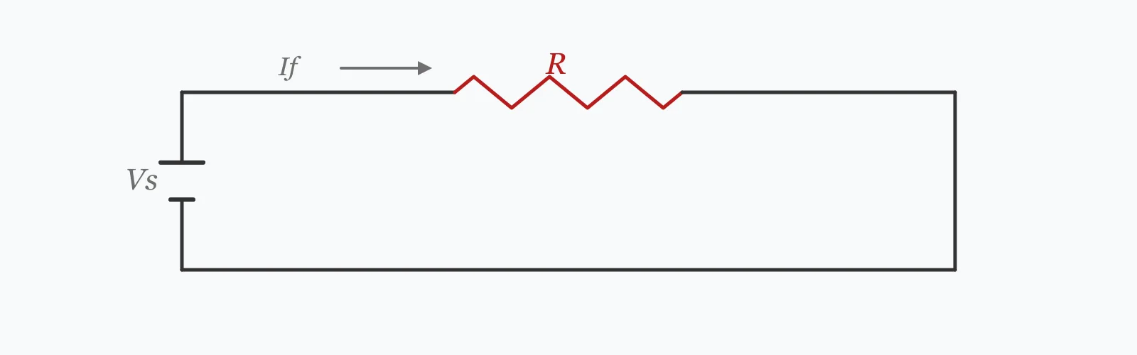
An LED needs a series resistor because it has no useful internal current limiting — a small voltage rise produces a large current rise. Enter the supply voltage, the LED forward voltage and the current you want, and get the ideal resistance, the nearest E12 preferred value you can actually buy, the current that value really delivers, and the power the resistor dissipates.
Calculator
Units:
V
Voltage across the LED and resistor in series
V
Red 1.8–2.2, yellow/green 2.0–2.4, blue/white 3.0–3.4
mA
20 mA is standard for indicator LEDs
LEDs sharing one resistor, wired in series
Calculation Result
Press Calculate for the ideal resistance, the nearest E12 value, the current that value actually gives, and the power the resistor dissipates. The gap between the requested and actual current is the price of using a preferred value.
Step-by-Step Solution
Preliminary design aid. Results follow the published formulas cited
below and are intended for estimating, study and early design. Final design must be
verified by a licensed Professional Engineer against the code in force for your project.
Key Benefits
✓Snaps to the E12 series, so the answer is a part you can buy
✓Reports the current the fitted resistor really delivers, not the target
✓Gives the resistor power dissipation for correct part selection
✓Handles LEDs in series and warns when headroom gets too small
✓Sensitivity chart shows how supply variation moves the current
✓Shareable links and CSV export for design records
What Is LED Resistor?
An LED is a diode, so its current rises exponentially with applied voltage above its forward threshold. Connect one directly across a supply and the current is limited only by the LED's small internal resistance and whatever the supply can deliver, which usually destroys it. A series resistor fixes this by absorbing the difference between the supply voltage and the LED's forward voltage, and the current then follows Ohm's law across that resistor rather than the diode's exponential curve.
Why the resistor value is coarse
Commercial resistors come in preferred series. E12 has twelve values per decade at roughly 20% intervals — 10, 12, 15, 18, 22, 27, 33, 39, 47, 56, 68, 82 — and E24 doubles that density. A calculated 495 Ω has no E12 member, so the nearest is 470 Ω, and the current comes out at 21.1 mA rather than the 20 mA requested. For an indicator LED that is irrelevant; for matched brightness across a panel it is not.
Where the power goes
The resistor dissipates the voltage it drops multiplied by the current, and that energy becomes heat with no useful output. One LED at 2.1 V on a 12 V supply leaves 9.9 V across the resistor, so 82.5% of the power is wasted. Five LEDs in series drop 10.5 V between them, leaving only 1.5 V for the resistor — 12.5% waste. Series strings are dramatically more efficient, which is why every LED lamp uses them.
Formula
R = (V_supply − n · V_f) / I_f
Series resistance for n LEDs, from the supply voltage, forward voltage and desired current
Related Formulas
P_R = (V_supply − n · V_f) · I_f
I_actual = (V_supply − n · V_f) / R_fitted
η = n · V_f / V_supply
Variable Definitions
Symbol
Variable
Unit
Description
V_supply
Supply Voltage
V
The voltage feeding the LED and resistor in series.
V_f
Forward Voltage
V
Voltage across one LED at the operating current. Red 1.8–2.2, blue and white 3.0–3.4.
I_f
Forward Current
mA
Desired LED current. 20 mA is the classic indicator value.
n
LEDs in Series
—
Number of LEDs sharing the same current through one resistor.
R
Series Resistance
Ω
The resistance that sets the current.
P_R
Resistor Power
mW
Heat dissipated in the resistor, which sets its required rating.
How to Use This Calculator
Use the forward voltage at your operating currentForward voltage rises with current, so the datasheet figure at 20 mA does not apply at 5 mA or 100 mA. It also varies by colour: red around 2.0 V, blue and white around 3.2 V, because the photon energy sets the band gap.
Check the LED's maximum continuous current20 mA is the traditional indicator figure, but modern high-efficiency LEDs are often brighter than needed at 5 mA and some are rated well above 20 mA. Running below maximum extends life and reduces heat.
Wire multiple LEDs in series, not parallelLEDs in series share the same current by definition. LEDs in parallel on one resistor do not: small differences in forward voltage make one take most of the current, and it fails first. Give each parallel branch its own resistor.
Read the actual current, not the requested oneThe E12 value rarely equals the calculated resistance, so the current shifts. A 10% difference is invisible on a single indicator and obvious across a row of them, where matched brightness matters.
Keep enough headroom across the resistorIf the resistor drops only a small fraction of the supply, normal LED-to-LED variation in forward voltage — commonly ±0.2 V — swings the current substantially. The calculator warns below about 15% headroom; at that point a constant-current driver is the right answer.
Worked Examples
Example 1
A single red LED with a 2.1 V forward voltage, run at 20 mA from a 12 V supply.
Step-by-Step Solution
Voltage across the resistor: 12 − 2.1 = 9.9 V
Ideal resistance: R = 9.9 / 0.020 = 495 Ω
Nearest E12 preferred value: 470 Ω
Actual current: 9.9 / 470 = 21.06 mA, 5.3% above the requested 20 mA
Resistor power: 9.9 × 0.02106 = 208.5 mW
A standard 0.25 W resistor is marginal at 208 mW in still air, so specify 0.5 W
Efficiency: the LED receives 2.1 V of the 12 V, so only 17.5% of the power does useful work — the resistor turns the other 82.5% into heat.
Example 2
Five of the same LEDs in series on the same 12 V supply, which is what an efficient design would do.
Step-by-Step Solution
Combined forward voltage: 5 × 2.1 = 10.5 V
Voltage across the resistor: 12 − 10.5 = 1.5 V
Ideal resistance: 1.5 / 0.020 = 75 Ω; nearest E12 value is 68 Ω
Resistor power: 1.5 × 0.02206 = 33.1 mW, against 208.5 mW for the single LED
Five times the light for a sixth of the resistor heat: the LEDs now receive 87.5% of the power instead of 17.5%.
But the design has become fragile. The resistor drops only 12.5% of the supply, so if the five LEDs happen to run 0.2 V high each — well within normal spread — the combined forward voltage becomes 11.5 V and the resistor sees just 0.5 V. The current would fall to about 7 mA, a third of intended.
This is the trade-off that constant-current drivers exist to resolve. They hold the current regardless of forward voltage spread, which is why every commercial LED lamp uses one rather than a dropper resistor.
Supply Voltage Sensitivity
How the required resistance and the resulting current respond to the supply. Note the steps in the resistance series — each one is a jump to the next E12 value, and the actual current jumps with it. The marker shows your current supply voltage.
Ideal Resistance vs Supply Voltage
Recomputed live from your inputs. The marker shows your current value.
Line chart of Ideal Resistance against Supply Voltage. The same
values are listed in the data table below.
Values plotted above, sampled across the supply voltage range.
How to Interpret Your Results
The actual current is what the LED experiences. The resistor power determines which physical part to fit, and the headroom determines how stable the whole arrangement is.
Actual LED Current: < 5Low current — long life
At your result mA the LED runs well below typical maximum ratings. Modern high-efficiency LEDs are often bright enough at this level, and running low reduces heat and extends life considerably.
Actual LED Current: 5 – 25Normal indicator range
your result mA is the standard operating range for indicator LEDs. Confirm it against the specific device's maximum continuous rating, which varies more than the traditional 20 mA figure suggests.
Actual LED Current: 25 – 100High current — check the rating
your result mA exceeds what most small indicator LEDs are rated for continuously. High-power devices tolerate it, but they need thermal management: LED life falls sharply with junction temperature.
Actual LED Current: ≥ 100Power LED territory
your result mA is power-LED current. A dropper resistor is the wrong approach at this level — it would waste watts as heat and offer no protection against thermal runaway. Use a constant-current driver.
At your result mW the resistor needs more than a standard 0.25 W part, which is marginal above about 125 mW in still air. Specify 0.5 W or 1 W, or reduce the dissipation by putting more LEDs in series.
Common Mistakes to Avoid
Connecting an LED without a series resistor
Why it matters:An LED's current rises exponentially with voltage above its forward threshold, so nothing limits it except the supply. A 3.2 V white LED on a 3.3 V supply may draw a fraction of an amp and fail within seconds.
✓How to avoid it:Always include current limiting — a resistor for indicators, a constant-current driver for anything at power levels. The LED sets the voltage; something else must set the current.
Putting LEDs in parallel on one resistor
Why it matters:Parallel LEDs share a voltage, not a current. The one with the lowest forward voltage takes a disproportionate share, runs hottest, drops its forward voltage further as it heats, and takes even more — a runaway that ends with it failing and the rest inheriting its current.
✓How to avoid it:Wire LEDs in series so they share one current, or give each parallel branch its own resistor. Never rely on matched devices to divide current.
Using a generic 2 V forward voltage
Why it matters:Forward voltage depends on colour, because the band gap sets the photon energy. Red is around 2.0 V but blue and white are around 3.2 V. Using 2 V for a white LED on a 5 V supply calculates 150 Ω when the correct value is nearer 90 Ω.
✓How to avoid it:Use the datasheet value at the intended current for the specific device. Where LEDs of different colours share a string, add their individual forward voltages.
Ignoring the resistor's power rating
Why it matters:The resistor converts everything it drops into heat. A single LED on 12 V dissipates 208 mW, which overheats a 0.25 W part in still air even though the figure is nominally within rating.
✓How to avoid it:Rate the resistor at roughly twice the calculated dissipation to allow for still air and ambient temperature. The calculator flags anything above 200 mW.
Leaving too little voltage across the resistor
Why it matters:With small headroom the current becomes extremely sensitive to forward voltage variation. In the five-LED example above, a 0.2 V spread per LED — entirely normal — cuts the current from 22 mA to about 7 mA.
✓How to avoid it:Keep at least 15 to 20% of the supply across the resistor, or use a constant-current driver, which is insensitive to forward voltage entirely.
Assuming the calculated resistance is what you will fit
Why it matters:E12 values step by roughly 20%, so a calculated 495 Ω becomes 470 Ω and the current rises 5.3%. Across a row of indicators fed by different values, the brightness difference becomes visible.
✓How to avoid it:Use the actual current the fitted value produces. Where matched brightness matters, use E24 or E96 values, or a series pair to hit the target more closely.
Practical Applications
▸Sizing series resistors for indicator LEDs
▸Designing LED strings for panels and backlights
▸Checking whether an existing resistor gives a safe current
▸Comparing series arrangements for efficiency
▸Selecting resistor power ratings
▸Deciding when a constant-current driver is needed instead
Industry Use Cases
Electronics design
Panel indicators use dropper resistors because simplicity outweighs the wasted power at 20 mA. The choice of E12 value is usually made once and reused, with brightness matching handled by picking the same value throughout rather than by precise current setting.
Lighting products
Commercial LED lamps put many devices in series so that the driver handles a high voltage at low current, minimising the fraction of power lost outside the LEDs. Constant-current control replaces the resistor entirely, because at these power levels resistive dropping is untenable.
Automotive and 12 V systems
Vehicle supplies vary widely — nominally 12 V but 14.4 V when charging and lower under load — so a dropper resistor gives a current that swings with the alternator. Series strings and current regulation are used for anything where brightness consistency matters.
Expert Tips
💡LEDs in series share current; LEDs in parallel do not.
💡Forward voltage is set by colour: red near 2.0 V, blue and white near 3.2 V.
💡The resistor turns everything it drops into heat, with no useful output.
💡One LED on 12 V wastes 82.5% of the power; five in series waste 12.5%.
💡Keep 15 to 20% of the supply across the resistor, or the current gets unstable.
💡Rate the resistor at about twice the calculated dissipation for still air.
Advantages & Limitations
Advantages
✓Returns a part number you can actually buy, not just an ideal value
✓Reports the real resulting current rather than the requested one
✓Gives the power dissipation, which decides the physical resistor size
✓Warns when headroom is too small for a resistive solution to be stable
✓Handles series strings, which is where the efficiency argument lives
Limitations
!Assumes a fixed forward voltage; in reality it varies with current and temperature
!Snaps to E12; E24 and E96 series give closer matches
!Does not model LED-to-LED forward voltage spread, only warns about its effect
!Assumes a stable DC supply — vehicle and battery supplies vary widely
!Takes no account of LED junction temperature, which lowers forward voltage as it rises
!Does not cover PWM dimming, where average and peak current differ
!A resistive solution is inappropriate above roughly 100 mA regardless of the arithmetic
One Supply, Different Numbers of LEDs
A 12 V supply with 2.1 V LEDs at a target of 20 mA. As LEDs are added, the resistor drops less, dissipates less and wastes less — but the arrangement becomes progressively more sensitive to forward voltage variation.
12 V supply, 2.1 V forward voltage, 20 mA target. Two of the five rows land exactly on an E12 value and give precisely 20 mA; the others are 5 to 10% high. The five-LED row is the most efficient and the least robust — only 1.5 V of headroom, so a normal 0.2 V spread per LED would collapse the current.
Subtract the LED forward voltage from the supply voltage and divide by the desired current. A 2.1 V LED at 20 mA on 12 V needs (12 − 2.1)/0.02 = 495 Ω, so a 470 Ω part.
Why does an LED need a resistor at all?
Because its current rises exponentially with voltage above the forward threshold, so nothing inherent limits it. Without a resistor the current is set only by what the supply can deliver, which usually destroys the LED.
What is a typical LED forward voltage?
It depends on colour, because the band gap sets the photon energy. Red is around 1.8 to 2.2 V, yellow and green 2.0 to 2.4 V, and blue and white 3.0 to 3.4 V.
What current should I run an LED at?
20 mA is the traditional figure for indicators, but modern high-efficiency devices are often bright enough at 5 mA. Running below maximum reduces heat and extends life; always check the specific device's rating.
Can I put LEDs in parallel with one resistor?
No. Parallel LEDs share voltage, not current, so the one with the lowest forward voltage takes a disproportionate share and fails first. Wire them in series, or give each branch its own resistor.
What resistor power rating do I need?
About twice the calculated dissipation, to allow for still air. A single LED on 12 V dissipates 208 mW, which needs a 0.5 W part — a 0.25 W one is marginal above roughly 125 mW.
Why is my LED dimmer than expected?
Usually because the fitted preferred value is higher than the calculated one, or because the forward voltage used in the calculation was too low. Check the actual current the fitted resistor gives at the real forward voltage.
How many LEDs can I put in series?
As many as leave sensible headroom across the resistor. On a 12 V supply with 2.1 V LEDs, five leaves only 1.5 V — enough to work, but too little to be stable against normal forward voltage variation.
When should I use a constant-current driver instead?
Above about 100 mA, where resistive dropping wastes real power, and whenever headroom is small or the supply varies. A driver holds the current regardless of forward voltage, which a resistor cannot.
What are E12 values?
The standard 10% resistor series — 10, 12, 15, 18, 22, 27, 33, 39, 47, 56, 68, 82 and their decade multiples. E24 doubles the density at 5% tolerance, and E96 is used for 1% precision parts.
Glossary
Forward voltage
The voltage across a conducting LED, set by its semiconductor band gap and therefore by its colour.
Forward current
The current through the LED, which determines its brightness.
Series resistor
A resistor in series with an LED that sets the current by absorbing the surplus voltage.
E12 series
The standard 10% preferred resistor values, twelve per decade.
E24 series
The standard 5% preferred resistor values, twenty-four per decade.
Constant-current driver
A circuit holding LED current steady regardless of forward voltage or supply variation.
Thermal runaway
The cycle where heating lowers forward voltage, raising current, which raises heating further.
Junction temperature
The temperature of the LED die, which governs both brightness and life.
Headroom
The voltage available across the resistor, which determines how stable the current is.
PWM dimming
Brightness control by switching the LED on and off rapidly rather than varying the current.
Scientific & Standards References
IEC 60063 — Preferred number series for resistors and capacitors — International Electrotechnical Commission
Schubert, E. F., Light-Emitting Diodes, 2nd Edition — Cambridge University Press
Horowitz, P. and Hill, W., The Art of Electronics, 3rd Edition — Chapter 1: Foundations — Cambridge University Press
IEC 62717 — LED modules for general lighting: Performance requirements — International Electrotechnical Commission
Cree and Lumileds LED application notes — Forward voltage and thermal derating — Cree LED and Lumileds
Conclusion
Sizing an LED resistor is a subtraction and a division, and everything worth knowing sits either side of it. Before: the forward voltage depends on colour, so a generic 2 V figure is wrong for anything blue or white by more than a volt. After: the E12 series steps by about 20%, so the fitted part rarely matches the calculation and the current shifts with it — 470 Ω in place of 495 Ω gives 21.06 mA rather than 20. The larger point is efficiency. A resistor turns everything it drops into heat, so a single LED on a 12 V supply delivers just 17.5% of the power to the light. Five in series raise that to 87.5%, but leave only 1.5 V of headroom, and at that point a normal spread in forward voltage swings the current by a factor of three. That is the boundary where a constant-current driver stops being an indulgence and becomes the correct answer.
Enter your supply, LED colour voltage and target current above to get a buyable value.