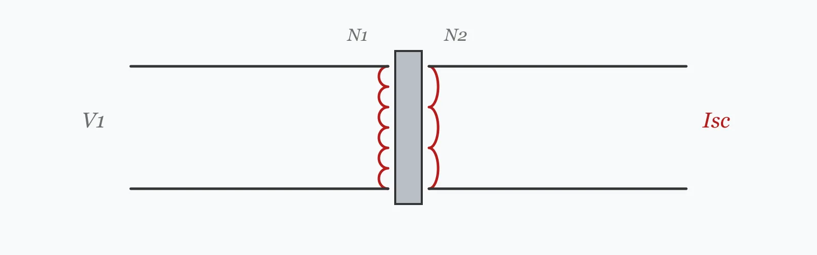
A transformer's percentage impedance is exactly the reciprocal of its fault level: a 5% transformer delivers twenty times its full load current into a terminal short. Enter the transformer rating, secondary voltage, impedance percentage and the cable run to the point of interest to get the full load current, the fault level at the terminals, the fault level at that point, and the total impedance.
Calculator
Units:
kVA
Rated apparent power of the supply transformer
V
Line-to-line voltage on the secondary
%
From the nameplate. 4 to 6% is typical for distribution transformers
m
Run from the transformer to the point of interest. Enter 0 for the terminals
mΩ/m
Per metre per phase. Roughly 0.5 for 120 mm², 1.5 for 35 mm² copper
Calculation Result
Press Calculate for the transformer's full load current, the prospective fault current at its terminals, the fault current at the end of the cable run, and the total impedance. Every protective device must have a breaking capacity at least equal to the fault level where it sits.
Step-by-Step Solution
Preliminary design aid. Results follow the published formulas cited
below and are intended for estimating, study and early design. Final design must be
verified by a licensed Professional Engineer against the code in force for your project.
Key Benefits
✓Derives the fault level directly from the transformer impedance percentage
✓Adds cable impedance to give the fault level at the point of interest
✓Shows both figures, which makes the effect of distance visible
✓Warns above 25 kA, the breaking capacity of many moulded-case devices
✓Flags when the fault level falls too low for reliable disconnection
✓Shareable links and CSV export for design records
What Is Short Circuit Current?
Prospective short circuit current is the current that would flow if a negligible-impedance fault occurred at a given point. It is not something the installation ever experiences in normal operation, but it determines two things that must both be satisfied: every protective device has to be able to interrupt it, and the fault energy let through before interruption has to be survivable by the cable.
Why impedance percentage is the reciprocal of fault level
A transformer's percentage impedance is defined as the percentage of rated voltage needed to drive rated current through the short-circuited winding. Turn that around: full voltage — a hundred percent — drives 100/Z% times rated current. A 5% transformer therefore gives twenty times full load current at its terminals, and a 4% transformer gives twenty-five. Lower impedance means better voltage regulation and a higher fault level, and the two requirements pull against each other.
Where the cable takes over
Transformer impedance is fixed, but cable impedance accumulates with distance, and it does so quickly. A 1000 kVA transformer at 5% has 8 mΩ of impedance; 30 m of cable at 0.5 mΩ/m adds 15 mΩ — nearly twice as much. That is why the fault level falls from 28.9 kA at the terminals to 10.0 kA thirty metres away, and why the transformer size matters far less at the end of a run than at the board.
Formula
Z_tx = (Z% / 100) · V² / S
Transformer impedance referred to the secondary, in ohms per phase
Related Formulas
I_sc = V / (√3 · Z_total)
I_sc,terminals = I_FL · 100 / Z%
Z_total = Z_tx + Z_cable
I²t ≤ k²S²
Variable Definitions
Symbol
Variable
Unit
Description
S
Transformer Rating
kVA
Rated apparent power of the supply transformer.
Z%
Impedance Percentage
%
Nameplate impedance. 4 to 6% is typical for distribution transformers.
V
Secondary Voltage
V
Line-to-line voltage on the secondary side.
I_FL
Full Load Current
A
Rated secondary current of the transformer.
I_sc
Fault Current
kA
Prospective short circuit current at the point considered.
Z_cable
Cable Impedance
mΩ
Impedance of the run from the transformer to the fault point.
How to Use This Calculator
Take the impedance percentage from the nameplateIt is a defining transformer parameter, typically 4 to 6% for distribution units. Do not estimate it: the fault level is inversely proportional to it, so a 4% transformer produces 25% more fault current than a 5% one of the same rating.
Use the secondary line-to-line voltageThe three-phase fault calculation uses line voltage with the √3 factor. For a 400 V secondary, enter 400 — not the 230 V phase-to-neutral value.
Enter the cable run to the point you are assessingFault level differs at every point in an installation. Enter zero for the transformer terminals, or the actual run to whichever board or device you are checking. The difference over even thirty metres is substantial.
Use an impedance figure appropriate to the cable sizeRoughly 0.5 mΩ/m for 120 mm² copper, 1.5 mΩ/m for 35 mm², and more for smaller sizes. The figure should include both resistance and reactance; for large cables reactance is the larger component.
Check the result against every device's breaking capacityA protective device whose breaking capacity is below the prospective fault current at its location will fail destructively when called upon. This is a rating check, not a margin — it must be satisfied, not approached.
Worked Examples
Example 1
A 1000 kVA transformer with 5% impedance feeds a 400 V board through 30 m of cable at 0.5 mΩ/m per phase.
Step-by-Step Solution
Full load current: I = 1,000,000 / (√3 × 400) = 1,443.4 A
Fault level at the terminals: 400 / (√3 × 0.008) = 28.87 kA
That is 28,868 / 1,443 = 20.0 times full load current, exactly 100/5
Cable impedance: 30 m × 0.5 = 15.00 mΩ, nearly twice the transformer's own
Total impedance: 8.00 + 15.00 = 23.00 mΩ
Fault level at the board: 400 / (√3 × 0.023) = 10.04 kA
Interpretation: thirty metres of cable has cut the fault level by 65%. Devices at the transformer need at least 28.87 kA breaking capacity; devices at this board need 10.04 kA.
Example 2
The same 30 m cable, but supplied from transformers of very different sizes — the comparison that shows how little transformer capacity matters at a distance.
Step-by-Step Solution
250 kVA at 5%: Z = 0.05 × 160,000/250,000 = 32.00 mΩ. Terminal fault level 7.22 kA.
1600 kVA at 5%: Z = 0.05 × 160,000/1,600,000 = 5.00 mΩ. Terminal fault level 46.19 kA.
The terminal fault levels differ by a factor of 6.4, exactly the ratio of the transformer ratings.
Now add the same 15 mΩ of cable. The 250 kVA case totals 47 mΩ and gives 4.91 kA; the 1600 kVA case totals 20 mΩ and gives 11.55 kA.
The ratio has collapsed from 6.4 to 2.35. A 6.4-fold increase in transformer capacity produced only a 2.35-fold increase in fault level thirty metres away.
The reason is visible in the impedance split. On the 250 kVA transformer the cable is 32% of the total; on the 1600 kVA one it is 75%. The larger the transformer, the more the cable dominates.
The practical consequence is that upgrading a transformer raises the fault duty at the main switchboard sharply while barely affecting distribution boards further out — so a supply upgrade often requires new main switchgear and nothing else.
Distance Sensitivity
Fault level falls steeply with the first few metres of cable and then flattens — the shape of a reciprocal. The impedance series rises linearly, which is what produces that curve. The marker shows your current cable length.
Fault Level at the Point vs Cable Length to Fault Point
Recomputed live from your inputs. The marker shows your current value.
Line chart of Fault Level at the Point against Cable Length to Fault Point. The same
values are listed in the data table below.
Values plotted above, sampled across the cable length to fault point range.
How to Interpret Your Results
The fault level at each point sets the breaking capacity required there. Too high and devices cannot interrupt it; too low and they may not disconnect a fault fast enough.
Fault Level at the Point: < 6Within common device ratings
A fault level of your result kA is within the 6 kA breaking capacity of standard domestic and light commercial devices. Check the low end too — a fault level that is too low may not operate the protection quickly enough on a long final circuit.
Fault Level at the Point: 6 – 10Standard commercial range
A fault level of your result kA needs devices rated 10 kA, which is the common commercial specification. Confirm the rating of every device at this location, including any that were added later.
Fault Level at the Point: 10 – 25Higher-rated switchgear needed
A fault level of your result kA requires devices specifically rated for it. Verify the breaking capacity marked on each device — this is a rating that must be satisfied outright, not approached with a margin.
Fault Level at the Point: ≥ 25Exceeds many moulded-case devices
A fault level of your result kA is above the 25 kA breaking capacity of many moulded-case circuit breakers. Consider current-limiting devices, cascading with an upstream device, or a higher-impedance transformer — and commission a full study to IEC 60909 rather than relying on this estimate.
Total Impedance: ≥ 200High loop impedance — check disconnection time
A total impedance of your result mΩ gives a low fault level. That eases the breaking capacity requirement but creates the opposite problem: the fault current may be too small to operate the protective device within the required disconnection time. Check the earth fault loop impedance separately.
Common Mistakes to Avoid
Using the transformer fault level everywhere in the installation
Why it matters:Fault level falls with distance, and quickly. In the example above, thirty metres of cable cut it from 28.87 kA to 10.04 kA — a 65% reduction. Applying the terminal figure throughout leads to specifying switchgear far above what is needed.
✓How to avoid it:Calculate at each point of interest. Using the terminal value is conservative for breaking capacity but expensive, and it tells you nothing about whether protection will operate at the far end.
Assuming a lower fault level is always better
Why it matters:It eases the breaking capacity requirement but makes disconnection harder. A protective device needs enough fault current to operate within the required time, and a long, high-impedance circuit may not deliver it. The result is a fault that persists.
✓How to avoid it:Check both ends of the problem: the breaking capacity at high fault levels, and the earth fault loop impedance and disconnection time at low ones.
Ignoring motor contribution
Why it matters:Running induction motors act briefly as generators when the supply voltage collapses, feeding current into the fault for the first few cycles. On a motor-heavy installation this can add three to five times the motors' combined rated current.
✓How to avoid it:Include it where motors form a significant share of the load. This calculation is a single-source estimate and does not account for it.
Overlooking the upstream network impedance
Why it matters:The transformer is not an infinite source. The impedance of the network feeding its primary adds to the total, which reduces the actual fault level a little below the value calculated from the transformer alone.
✓How to avoid it:Obtain the network fault level from the distribution operator for a formal study. Neglecting it is conservative for breaking capacity, which is why the simplified calculation is acceptable for screening.
Specifying a low-impedance transformer without checking downstream
Why it matters:Low impedance gives better voltage regulation, which is desirable, but it raises the fault level proportionally. A 4% transformer produces 25% more fault current than a 5% one of the same rating, and that may exceed the switchgear already installed.
✓How to avoid it:Treat impedance as a system decision rather than a transformer one. Replacing a transformer with a lower-impedance unit of the same rating can invalidate the switchgear downstream of it.
Checking breaking capacity but not let-through energy
Why it matters:A device may be able to interrupt the fault and still allow enough energy through to damage the cable while doing so. The adiabatic check compares the I²t let through against what the conductor cross-section can absorb.
✓How to avoid it:Verify the adiabatic condition as well as the breaking capacity. Current-limiting devices help specifically because they cut the let-through energy, not just the peak current.
Practical Applications
▸Specifying breaking capacity for protective devices
▸Checking existing switchgear against a revised supply
▸Assessing the effect of a transformer upgrade on downstream boards
▸Screening fault levels before a formal IEC 60909 study
▸Verifying that cable sizes survive the let-through energy
▸Comparing transformer impedance options at design stage
Industry Use Cases
Industrial installations
Fault levels are calculated at every distribution board, because switchgear rated for the main board would be needlessly expensive further out. The steep fall over the first tens of metres means sub-boards often need a rating one or two steps below the main.
Supply upgrades
Replacing a transformer with a larger unit raises the fault level at the main switchboard almost in proportion, while barely moving it at remote boards. The upgrade therefore frequently requires new main switchgear and no change at all elsewhere.
Renewable and standby generation
Generators and inverters contribute to fault current with quite different characteristics from a transformer — a generator's contribution decays over the first cycles, and an inverter's is limited electronically to little above rated current. Both need modelling explicitly rather than being added as another source.
Expert Tips
💡Fault level at the terminals is full load current times 100/Z%.
💡A 5% transformer gives 20× full load; a 4% one gives 25×.
💡Thirty metres of cable cut the example fault level by 65%.
💡Lower impedance means better regulation and a higher fault level — they conflict.
💡The bigger the transformer, the more the cable dominates the total impedance.
💡Too low a fault level is a problem too: protection may not disconnect in time.
Advantages & Limitations
Advantages
✓Derives the fault level from the nameplate impedance, which is always available
✓Reports terminal and downstream fault levels together, showing the effect of distance
✓Gives the impedance split, which explains why the answer behaves as it does
✓Warns at 25 kA, where common moulded-case devices run out
✓Fast enough to check every board during a design review
Limitations
!A simplified single-source calculation using impedance magnitudes
!Neglects the network impedance upstream of the transformer — conservative, but approximate
!Does not include motor contribution, which matters on motor-heavy sites
!Does not resolve resistance and reactance separately, as IEC 60909 requires
!Applies no voltage factor c, which a formal study uses to bound the result
!Gives symmetrical RMS current, not the asymmetrical peak that mechanical stresses depend on
!Does not check let-through energy or the adiabatic condition for cables
How Distance Erodes the Fault Level
A 1000 kVA transformer at 5% impedance on 400 V, with 8 mΩ of its own impedance. Each row adds cable at 0.5 mΩ/m. The first ten metres do more than the next ninety.
1000 kVA, 400 V, 5% impedance, 0.5 mΩ/m cable. The first ten metres remove 38% of the fault level; the following ninety metres remove a further 48 percentage points, reaching 86%. Beyond about sixty metres the transformer has become almost irrelevant — the cable is 79% of the impedance and rising.
Find the transformer impedance from Z = (Z%/100)·V²/S, add the cable impedance, then divide the voltage by √3 times the total. A 1000 kVA 5% transformer on 400 V gives 28.87 kA at its terminals.
What does transformer impedance percentage mean?
The percentage of rated voltage needed to drive rated current through the short-circuited winding. Because full voltage is a hundred percent, the fault level is 100/Z% times full load current — twenty times for a 5% transformer.
Why does fault current fall with distance?
Cable impedance adds in series with the transformer's. It accumulates linearly with length while the fault current falls as the reciprocal, which is why the first few metres matter far more than the last.
What breaking capacity do I need?
At least the prospective fault current at the device's location. It is a rating that must be satisfied outright — a device that cannot interrupt the fault it sees fails destructively instead of protecting the circuit.
Is a lower fault level always safer?
No. It eases the breaking capacity requirement but can prevent protection operating fast enough. A long, high-impedance circuit may not pass enough fault current to trip its device within the required disconnection time.
How does transformer size affect the fault level?
At the terminals, almost in proportion — 250 kVA gives 7.22 kA and 1600 kVA gives 46.19 kA at the same impedance. Thirty metres away the same comparison is only 4.91 against 11.55 kA, because the cable dominates.
What is motor contribution to fault current?
Running induction motors briefly act as generators when the supply collapses, feeding the fault for the first few cycles. On motor-heavy sites this can add three to five times the motors' combined rated current.
What is IEC 60909?
The international standard for short circuit current calculation. It resolves resistance and reactance separately, applies a voltage factor, includes network impedance and motor contribution, and distinguishes the initial symmetrical, peak and breaking currents.
What is the adiabatic check?
A verification that the energy let through by the protective device before it clears — the I²t — does not exceed what the conductor can absorb without damage. A device can have adequate breaking capacity and still let through enough energy to destroy the cable.
Should I use a higher-impedance transformer to reduce fault level?
It is one option, and it is sometimes done where existing switchgear cannot be replaced. The cost is worse voltage regulation, since the same impedance that limits the fault also produces more voltage drop under normal load.
Glossary
Prospective short circuit current
The current that would flow if a negligible-impedance fault occurred at a given point.
Breaking capacity
The maximum fault current a protective device can interrupt safely.
Impedance percentage
The percentage of rated voltage that drives rated current through a short-circuited transformer winding.
Fault level
The prospective short circuit current at a point, usually quoted in kA.
Let-through energy
The I²t a device allows to pass before clearing a fault.
Adiabatic check
Verification that a cable can absorb the let-through energy without damage.
Current limiting
A device characteristic that clears fast enough to cut the peak current and let-through energy.
Cascading
Relying on an upstream device to assist a downstream one in clearing a fault beyond its own rating.
Motor contribution
Fault current fed by running motors acting momentarily as generators.
IEC 60909
The international standard method for calculating short circuit currents.
Scientific & Standards References
IEC 60909-0 — Short-circuit currents in three-phase AC systems: Calculation of currents — International Electrotechnical Commission
IEC 60947-2 — Low-voltage switchgear and controlgear: Circuit-breakers — International Electrotechnical Commission
IEEE 551 (Violet Book) — Calculating Short-Circuit Currents in Industrial and Commercial Power Systems — Institute of Electrical and Electronics Engineers
BS 7671 — Requirements for Electrical Installations, Chapter 43 and Appendix 4 — Institution of Engineering and Technology
IEC 60076-5 — Power transformers: Ability to withstand short circuit — International Electrotechnical Commission
Conclusion
The transformer nameplate gives the fault level away directly, because impedance percentage is its reciprocal: 5% means twenty times full load current at the terminals. What happens after that is governed by cable, and the table above shows how fast. Thirty metres cuts a 28.87 kA fault level to 10.04 kA, and beyond sixty metres the cable holds 79% of the total impedance — at which point the transformer has become almost irrelevant to the answer. That has a practical consequence worth carrying: upgrading a supply transformer raises the duty on the main switchboard sharply and barely touches boards further out. The other thing to keep in view is that the problem has two ends. A fault level too high for a device's breaking capacity is dangerous, but so is one too low to operate the protection within the required disconnection time.
Enter your transformer data and cable run above to get the fault level where it matters.