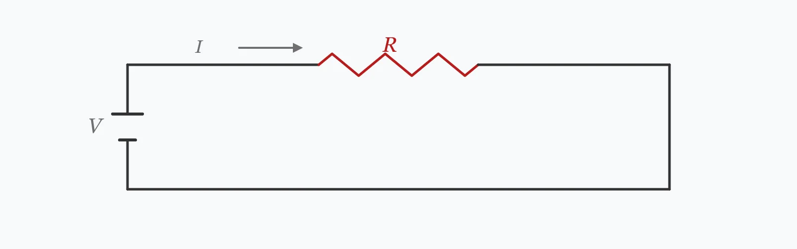
Ohm's law states V = I × R. Supply any two of the three and this calculator returns the third, along with the power dissipated. Power follows from whichever pair you gave: P = VI, P = I²R or P = V²/R — all three give the same answer for a resistive circuit.
Calculator
Units:
V
Leave at 0 to solve for voltage from current and resistance
A
Leave at 0 to solve for current
Ω
Leave at 0 to solve for resistance
Calculation Result
Press Calculate and the missing quantity is solved from the two you supplied, together with the power. Leave the value you want calculated at zero — at least two of the three must be non-zero.
Step-by-Step Solution
Preliminary design aid. Results follow the published formulas cited
below and are intended for estimating, study and early design. Final design must be
verified by a licensed Professional Engineer against the code in force for your project.
Key Benefits
✓Solves for whichever of the three quantities you leave blank
✓Returns power alongside, computed from whichever pair you supplied
✓Handles all three input combinations from one form
✓Includes the four power forms and when each is most convenient
✓Sensitivity chart shows the quadratic relationship between current and power
✓Shareable links and CSV export for circuit records
What Is Ohm's Law?
Ohm's law states that the current through a conductor is proportional to the voltage across it and inversely proportional to its resistance: I = V/R, usually written V = IR. Resistance is the constant of proportionality, measured in ohms, and it describes how strongly a material opposes the flow of charge. The law is a material property observation rather than a fundamental law of physics — it holds for metals and for most practical conductors, and fails for many other things.
The power relationships
Power dissipated in a resistive element is P = VI. Substituting Ohm's law gives two more forms: P = I²R and P = V²/R. All three are equivalent for a resistor, and which is most useful depends on what you know. P = I²R is the one worth remembering, because it makes the square relationship visible — a cable carrying twice the current dissipates four times the heat, which is the single most consequential fact in electrical installation design.
Where the law stops holding
Ohm's law describes linear resistive elements. Diodes, transistors and LEDs are non-linear — their resistance changes with the applied voltage, so no single value describes them. It also applies to DC or to purely resistive AC circuits; where inductance or capacitance is present, the opposition to current is impedance rather than resistance, and voltage and current fall out of phase. And resistance itself varies with temperature: copper rises about 0.4% per degree, so a hot conductor is a more resistive one.
Formula
V = I × R
Ohm's law relating voltage, current and resistance
Related Formulas
P = V × I
P = I² × R
P = V² / R
R_T = R₀(1 + α ΔT)
Variable Definitions
Symbol
Variable
Unit
Description
V
Voltage
V
Potential difference across the element, the driving force for current.
I
Current
A
Rate of charge flow through the element.
R
Resistance
Ω
Opposition to current flow, the ratio of voltage to current in a linear element.
P
Power
W
Rate of energy conversion, dissipated as heat in a resistive element.
α
Temperature Coefficient
/°C
Fractional resistance change per degree; 0.00393 for copper, 0.00403 for aluminium.
How to Use This Calculator
Leave the unknown at zeroEnter any two of voltage, current and resistance, and set the third to zero. At least two must be non-zero, or the calculator has nothing to work from.
Use consistent unitsVolts, amperes and ohms give watts directly. Milliamps and kilohms are common in electronics — convert before entering, or the power result will be out by a factor of a thousand in either direction.
Read the power result carefullyThe power shown is dissipated in the resistance, which for a heating element is the useful output and for a cable is pure loss. The same number means opposite things depending on what the resistance represents.
Check the resistance is really linearOhm's law describes linear elements. A lamp filament, a diode or a motor winding under load all have effective resistances that change with conditions, so a single value only describes one operating point.
Allow for temperature on precise workCopper resistance rises about 0.4% per degree Celsius. A conductor running at 70 °C rather than 20 °C has around 20% more resistance than its published cold value, which matters for both voltage drop and loss calculations.
Worked Examples
Example 1
A 12 V supply drives 2 A through a load. Find the resistance and the power dissipated.
Step-by-Step Solution
Voltage and current are given, so the calculator solves for resistance
Resistance: R = V/I = 12 / 2 = 6.0000 Ω
Power: P = V × I = 12 × 2 = 24.0000 W
Cross-check with the other two forms:
P = I²R = 2² × 6 = 4 × 6 = 24 W
P = V²/R = 12² / 6 = 144 / 6 = 24 W
All three agree, as they must for a linear resistive element.
Note that entering any two of 12 V, 2 A and 6 Ω returns the same complete set — the three are not independent.
Example 2
A loose terminal introduces 0.1 Ω into a circuit carrying 30 A. This is the case where the square relationship becomes a safety matter rather than an efficiency one.
Step-by-Step Solution
Resistance and current are given, so the calculator solves for voltage
Voltage across the joint: V = I × R = 30 × 0.1 = 3.0000 V
Power dissipated at the joint: P = I²R = 30² × 0.1 = 900 × 0.1 = 90.0000 W
Ninety watts is being released in the volume of a single terminal — comparable to a soldering iron, and with nowhere for the heat to go.
Now halve the current to 15 A: P = 15² × 0.1 = 22.5 W, a quarter of the heat from half the current.
That square relationship is why loose connections fail catastrophically at high current and merely warm up at low current, and why the same fault is benign in a lighting circuit and dangerous in a cooker circuit.
It is also why thermal imaging surveys of switchboards look for hot joints: a connection dissipating tens of watts is visible long before it fails.
Current Sensitivity
With resistance fixed, voltage rises linearly with current while power rises with its square — the two curves diverge sharply. That divergence is why current, not power, is what cables are rated on. The marker shows your current value.
Power (P) vs Current (I)
Recomputed live from your inputs. The marker shows your current value.
Line chart of Power (P) against Current (I). The same
values are listed in the data table below.
Values plotted above, sampled across the current (i) range.
How to Interpret Your Results
Power is the output worth reading, because it tells you what the circuit does with the energy — useful work in a heater, wasted heat in a cable, and a hazard in a bad connection.
Power (P): < 1Low power — signal or control level
A power of your result W is in the range of signal, sensor and control circuits. Heat dissipation is not a concern, but check that any resistor is rated above this figure with margin — components are commonly derated to half their nominal rating.
Power (P): 1 – 100Component power range
A power of your result W requires a component rated for it with margin. If this power is being dissipated in a cable or connection rather than a load, it is waste heat and worth investigating.
Power (P): 100 – 3000Substantial power — check where the heat goes
A power of your result W is appliance-scale. In a load this is the useful output; in a conductor or joint it is a serious fault. Confirm which, and if it is a loss, that the resistance is where you intended it.
Power (P): ≥ 3000High power
A power of your result W requires substantial conductors and switchgear. Verify the current against the cable rating, and remember that heat generated in a conductor grows with the square of current — a modest overload is a large thermal one.
Resistance (R): < 1Very low resistance
A resistance of your result Ω is low — the range of conductors, connections and shunts rather than loads. At this level, measurement requires a four-wire technique, since ordinary test lead resistance is of the same order.
Common Mistakes to Avoid
Mixing units without converting
Why it matters:Electronics works in milliamps and kilohms, power engineering in amps and ohms. Entering 500 mA as 500 rather than 0.5 overstates the current a thousandfold and the power by the same factor.
✓How to avoid it:Convert everything to volts, amps and ohms before entering. Milliamps divided by 1,000; kilohms multiplied by 1,000.
Applying Ohm's law to a non-linear device
Why it matters:Diodes, LEDs, lamps and transistors do not have a fixed resistance. A red LED drops around 2 V almost regardless of current, so dividing voltage by current gives a number that changes at every operating point.
✓How to avoid it:Use the device's characteristic curve or its published forward voltage. For an LED, size the series resistor from the supply voltage minus the forward drop, divided by the desired current.
Using resistance where impedance is needed
Why it matters:In an AC circuit with inductance or capacitance, current is opposed by impedance rather than resistance, and voltage and current fall out of phase. Ohm's law in its simple form applies only to the resistive case.
✓How to avoid it:Use Z instead of R for AC circuits with reactive elements, and remember that real power then requires the power factor: P = VI·cos θ, not VI.
Ignoring the temperature coefficient
Why it matters:Copper resistance rises about 0.4% per degree. A cable at its 70 °C rated operating temperature has roughly 20% more resistance than the 20 °C table value, so voltage drop and losses are both understated.
✓How to avoid it:Use the resistance at operating temperature for voltage drop and loss calculations. Cable tables generally publish both the 20 °C and the operating-temperature values.
Underestimating the effect of a small series resistance
Why it matters:Because power goes as the square of current, a resistance too small to notice at low current becomes dangerous at high current. A 0.1 Ω joint dissipates 0.1 W at 1 A and 90 W at 30 A.
✓How to avoid it:Evaluate connection resistance at the actual operating current, not in isolation. This is exactly what thermographic surveys of switchgear are looking for.
Confusing power rating with power dissipated
Why it matters:A resistor's rating is the power it can dissipate without overheating, not what it will dissipate. Fitting a 0.25 W resistor into a circuit that will put 1 W through it destroys it regardless of the resistance being correct.
✓How to avoid it:Compute the dissipated power and select a component rated above it, conventionally with a factor of two for continuous operation.
Practical Applications
▸Sizing series resistors for LEDs and control circuits
▸Calculating current draw from a known load resistance
▸Determining power dissipation in components and conductors
▸Diagnosing connection resistance from measured voltage drop
▸Estimating heating element output from supply voltage
▸Verifying shunt and sense resistor values
Industry Use Cases
Electrical installation and maintenance
Thermographic surveys of switchboards look for joints dissipating tens of watts. Because power goes as the square of current, a connection that is merely warm at light load becomes a fire risk at full load, so surveys are conducted under load rather than during a shutdown.
Electronics design
Series resistor sizing for LEDs is the archetypal application, but with a twist: the LED's forward voltage must be subtracted first because it is not ohmic. Ohm's law then applies to the resistor alone, which is the linear part of the circuit.
Battery and power systems
Internal resistance determines how much a battery's terminal voltage sags under load. Measuring the voltage drop at a known current gives the internal resistance directly, and its rise over time is the standard indicator of cell ageing.
Expert Tips
💡P = I²R is the form worth remembering — it makes the square relationship with current visible.
💡Halving the current quarters the heat, which is why cables are rated on current rather than power.
💡Copper resistance rises 0.4% per degree; a hot cable is a more resistive one.
💡Any two of V, I and R determine the third — they are not independent quantities.
💡For AC with reactance, use impedance and include the power factor: P = VI·cos θ.
💡Derate resistors to about half their rating for continuous duty.
Advantages & Limitations
Advantages
✓Solves for any of the three quantities from the other two
✓Returns power automatically, computed consistently whichever pair was supplied
✓Applies to any linear resistive element regardless of scale
✓Simple enough to verify mentally
✓Underpins nearly every other electrical calculation
Limitations
!Applies to linear resistive elements only, not diodes, lamps or semiconductors
!Valid for DC or purely resistive AC; reactive circuits need impedance and power factor
!Assumes constant resistance, ignoring the 0.4% per degree temperature coefficient of copper
!Requires at least two of the three quantities to be non-zero
!Does not distinguish useful output from waste heat — both appear as power
!Takes no account of component power ratings
!Assumes steady state; transient and switching behaviour needs a different treatment
The Four Ohm's Law Relationships
Ohm's law and the power equation combine into twelve rearrangements, but four cover almost everything. Which is most convenient depends on which two quantities you happen to know.
All twelve forms follow from V = IR and P = VI. The calculator uses the first three rows, taking whichever pair of V, I and R you supply.
It states that voltage equals current times resistance, V = IR. Rearranged, current is voltage divided by resistance, and resistance is voltage divided by current. It applies to linear resistive elements such as metal conductors and ordinary resistors.
How do I calculate power from Ohm's law?
Three equivalent forms: P = VI, P = I²R and P = V²/R. All give the same result for a resistive element. A 12 V supply driving 2 A through 6 Ω dissipates 24 W by any of them.
Why does power go as the square of current?
Because P = I²R. Doubling the current doubles the voltage drop across a fixed resistance as well, and power is their product. That is why a cable carrying twice the current generates four times the heat.
Does Ohm's law apply to AC circuits?
In its simple form, only to purely resistive AC circuits. Where inductance or capacitance is present, current is opposed by impedance rather than resistance, and real power becomes P = VI·cos θ, with the power factor accounting for the phase difference.
Does Ohm's law apply to LEDs?
Not to the LED itself, which is non-linear and drops a roughly fixed forward voltage regardless of current. It applies to the series resistor: subtract the LED's forward voltage from the supply, then divide by the desired current.
How does temperature affect resistance?
Copper rises about 0.393% per degree Celsius and aluminium 0.403%. A conductor at its 70 °C rated temperature has roughly 20% more resistance than its 20 °C table value, which matters for voltage drop and loss calculations.
Why is a loose connection dangerous?
Because it adds resistance in series with the full load current, and the heat generated goes as the square of that current. A 0.1 Ω joint dissipates only 0.1 W at 1 A but 90 W at 30 A — concentrated in a terminal with nowhere to shed it.
What resistor power rating do I need?
Compute the dissipated power with P = I²R or V²/R, then choose a component rated above it. Convention is a factor of two for continuous operation, since a resistor at its exact rating runs very hot.
Can I measure very low resistances with an ordinary meter?
Not reliably. Below about 1 Ω, the resistance of the test leads becomes comparable to what you are measuring. Use a four-wire Kelvin measurement, which separates the current-carrying and voltage-sensing paths.
What is the difference between resistance and impedance?
Resistance opposes current and dissipates energy; reactance from inductance or capacitance opposes changing current and stores it. Impedance is their combination, and it introduces a phase difference between voltage and current that resistance alone does not.
Glossary
Ohm's law
The relationship V = IR between voltage, current and resistance in a linear element.
Voltage
The potential difference driving current through a circuit, measured in volts.
Current
The rate of charge flow, measured in amperes.
Resistance
Opposition to current flow in a linear element, measured in ohms.
Power
Rate of energy conversion, dissipated as heat in a resistive element.
Impedance
The AC equivalent of resistance, combining resistance and reactance and introducing a phase shift.
Temperature coefficient
The fractional change in resistance per degree of temperature rise; 0.00393 per °C for copper.
Non-linear element
A component whose resistance varies with applied voltage, such as a diode or lamp filament.
Four-wire measurement
A technique separating current and voltage paths, needed to measure resistances below about 1 Ω accurately.
Scientific & Standards References
Ohm, G. S., Die galvanische Kette, mathematisch bearbeitet (1827) — T. H. Riemann, Berlin
IEC 60050-121 — International Electrotechnical Vocabulary: Electromagnetism — International Electrotechnical Commission
Horowitz, P. & Hill, W., The Art of Electronics, 3rd Edition — Chapter 1: Foundations — Cambridge University Press
IEC 60228 — Conductors of insulated cables, including temperature coefficients — International Electrotechnical Commission
NFPA 70B — Recommended Practice for Electrical Equipment Maintenance, thermographic surveys — National Fire Protection Association
Conclusion
Ohm's law gives V = IR, and any two of the three quantities determine the third along with the power. The form worth carrying is P = I²R, because it makes visible the relationship that governs electrical installation design: heat grows with the square of current, so halving the current quarters the loss. It is also what makes a small series resistance dangerous — a 0.1 Ω joint releases 0.1 W at 1 A and 90 W at 30 A. Two boundaries are worth respecting: the law describes linear elements only, so it applies to the resistor in an LED circuit but not to the LED, and in AC circuits with reactance it becomes an impedance relationship with a power factor attached.
Try your own circuit above, then sweep the current in the chart to watch power outpace voltage.